© 2022 Hoymiles Power Electronics Inc. All rights reserved.
13
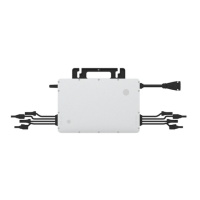
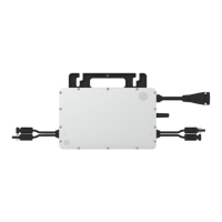
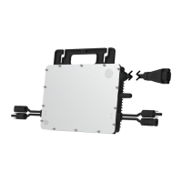
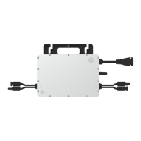
Single-phase Microinverter HMS-1600/1800/2000-4T-NA
5. Microinverter Installation
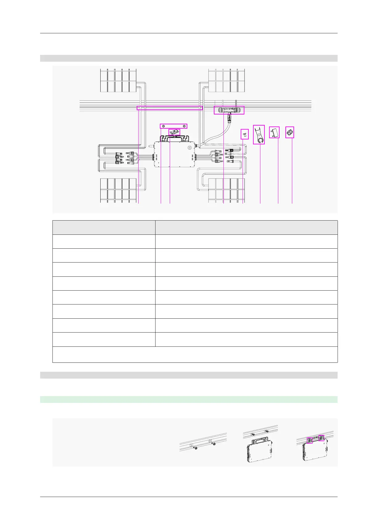
5.1 Accessories
E FD HGB C
Description
A AC Trunk Cable, 12/10 AWG Cable
B M8 × 25 screws (Prepared by the installer)
C Grounding Electrode
D AC Trunk Connector
E AC Trunk Connector Unlock Tool
F AC Trunk Port Disconnect Tool
G AC Trunk Port Cap
H AC Trunk End Cap
*Note: All accessories above are not included in the package and should be purchased separately.
About Installation
A
5.2 Installation Steps
The order of Step 1 and Step 2 can be reversed according to your planned needs.
Step 1. Plan and Install the Microinverter
A ) Mark the position of each microinverter on the rail according to the PV module layout.
B ) Fix the screws on the rail.
C ) Hang the microinverter on the
screws, and tighten the screws. The
silver cover side of the microinverter
should be facing the panel.
Mounting Torque : 9 N·m
 Loading...