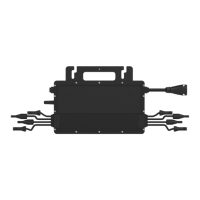
This document outlines the installation, operation, and maintenance of the Hoymiles Single-phase Microinverter, specifically the HMS-1800-4T and HMS-2000-4T models. These microinverters are integral components of a photovoltaic (PV) system, designed to convert direct current (DC) generated by PV modules into alternating current (AC) suitable for feeding into the public grid.
Function Description
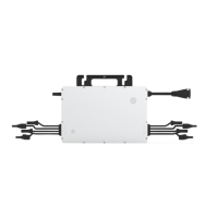
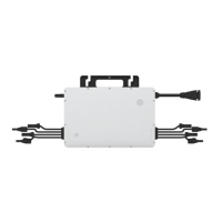
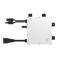
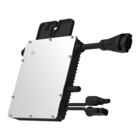
The Hoymiles microinverter system is comprised of multiple microinverters, each independently connected to up to four PV modules. This independent operation is a key feature, ensuring maximum power generation from each PV module. Even if one module fails or is shaded, it only affects its own power generation, leaving the rest of the system unaffected. This design significantly enhances the flexibility and reliability of the overall PV system. The microinverter monitors the current, voltage, power output, and power generation of each module, enabling module-level data monitoring. Furthermore, the microinverter operates with a low DC voltage (a few tens of volts), which substantially reduces potential safety hazards. The HMS-1800-4T and HMS-2000-4T models are specifically compatible with Hoymiles gateway DTU-Pro-S and DTU-Lite-S for monitoring purposes.
Usage Features
The microinverter offers a wide maximum power tracking voltage range and flexible module configuration. The HMS-2000 model boasts an output power of up to 2000 VA, making it one of the highest-ranking 4-in-1 microinverters. Each microinverter connects to a maximum of four PV modules, each with independent Maximum Power Point Tracking (MPPT) and monitoring capabilities. This independent tracking allows for greater energy harvest and simplifies maintenance. The Hoymiles 4-in-1 unit microinverter is particularly well-suited for PV systems with an uneven number of PV modules.
A notable feature of these microinverters is their integration of Sub-1G technology for communication. Sub-1G wireless technology operates on the 868 MHz or 915 MHz band, offering a substantially larger range (1.5 to 2 times more distance coverage) compared to 2.4 GHz technologies like Wi-Fi or Zigbee. This technology also provides better interference suppression performance, making communication between the microinverters and the DTUs more stable, especially in industrial or commercial PV power plants. Additionally, Sub-1G wireless consumes less power, making it an efficient choice for rooftop PV power stations due to its long range and robust interference suppression.
Installation of the microinverter requires careful attention to placement. It should be installed under the PV module to avoid direct sunlight, rain, snow buildup, and UV exposure. The silver side of the microinverter should face upwards towards the PV module. A minimum of 2 cm of space around the enclosure is necessary to ensure adequate ventilation and heat dissipation. The DC input port of the microinverter connects directly to a PV module. If the DC cable length is insufficient, a DC extension cable can be used, adhering to local regulations and not exceeding 5 meters to prevent impact on power production.
The AC Trunk Cable, provided by Hoymiles in 12AWG or 10AWG, connects the microinverter to the distribution box. The number of microinverters per AC branch is limited by the cable's current carrying capacity, with specific limits provided for 12AWG and 10AWG cables at different voltages. The installation process involves marking microinverter positions on the rail, fixing screws, and hanging the microinverter with the silver cover facing the panel. Grounding can be achieved directly through the AC cable's earth wire, or optionally via grounding brackets for specific regional requirements.
Connecting the AC Trunk Cable involves disassembling the AC Trunk Connector, inserting the cable segments, and tightening screws to ensure a secure connection. An AC Trunk End Cap is used at one end of the AC Trunk Cable, and an AC end cable connects to the distribution box at the other. Any vacant AC Trunk Ports must be sealed with an AC Trunk Port Cap to ensure water and dust protection. After connecting the AC Sub Connector from the microinverter to the AC Trunk Connector, the AC end cable is wired to the local grid network. An installation map is created by affixing serial number labels from each microinverter to their respective locations. Finally, PV modules are mounted above the microinverters, and their DC cables are connected to the microinverter's DC input side. The system is energized by turning on the AC breaker for the branch circuit and then the main AC breaker for the house, allowing power generation to commence within approximately two minutes. A monitoring system is then set up using the DTU and S-Miles Cloud.
Maintenance Features
Routine maintenance of the microinverter system should only be performed by authorized personnel. Personal protective equipment, including gloves and goggles, must be used during maintenance operations. Regular checks of environmental and logistic conditions are essential to ensure the equipment is not exposed to adverse weather or covered by foreign bodies. Any operational anomalies must be addressed, and the equipment should not be used if problems are found until normal conditions are restored. An annual inspection of various components and cleaning with a vacuum cleaner or special brushes are recommended.
Troubleshooting guidance is provided through a comprehensive list of alarm codes and their corresponding handling suggestions. These include issues related to over-temperature protection, remote shutdown, grid configuration errors, firmware errors, abnormal bias, offline status, grid overvoltage/undervoltage/overfrequency/underfrequency, rapid grid frequency change rate, power grid outage, grid disconnection, island detection, and input overvoltage/undervoltage for specific MPPT ports. The LED indicator status provides visual cues for the microinverter's operational state, including start-up success/failure, power production (normal or with abnormal input), invalid AC grid, hardware failure, and firmware issues.
For on-site inspection by qualified installers, a sequence of steps is provided to troubleshoot malfunctioning microinverters. This includes checking utility voltage and frequency, verifying connections to the utility grid, ensuring proper interconnection between microinverters, confirming AC breaker functionality, checking DC connections, and verifying PV module DC voltage. Users are explicitly warned against attempting to repair the microinverter themselves; if troubleshooting fails, the unit should be returned to the factory for replacement. The AC output wiring harness is not replaceable, and if damaged, the equipment should be scrapped. Maintenance operations must be carried out with the equipment disconnected from the grid and PV modules obscured or isolated. Cleaning should avoid filamentary materials or corrosive products.
Replacing a microinverter involves de-energizing the AC branch circuit breaker, removing and covering the PV module, verifying no current in DC wires, using DC and AC disconnect tools, loosening fixing screws, and removing the microinverter from the racking. For replacement in the monitoring platform, the new microinverter's serial number is recorded, and the installation steps for the replacement unit are followed. The monitoring platform allows users to access the "Device List" page, find the replaced device, and use the "Replace Device" function to input the new serial number and complete the station change.
Decommissioning involves disconnecting the inverter from DC input and AC output, removing all connection cables, and detaching the microinverter from its frame. For storage, the microinverter should be packed in its original packaging or a suitable carton box and stored indoors with good ventilation. Transportation requires proper packaging to protect components from shocks, humidity, and vibration. Customers should inspect components upon receipt and contact the supplier for any damage or missing parts. The microinverter storage temperature range is -40 to 85°C. Finally, microinverters must be disposed of properly according to local regulations to prevent environmental harm.