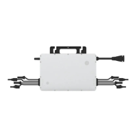
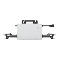
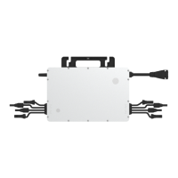
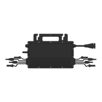
This document describes the Hoymiles Single-phase Microinverter, specifically the HMS-300-1T, HMS-350-1T, HMS-400-1T, HMS-450-1T, and HMS-500-1T models. These microinverters are designed to convert direct current (DC) generated by photovoltaic (PV) modules into alternating current (AC) for feeding into the public grid.
Function Description
The Hoymiles microinverter system is comprised of a group of microinverters, each connected to a single PV module (a 1-in-1 configuration). This design allows each microinverter to operate independently, ensuring maximum power generation from each individual PV module. This independent operation means that if one PV module fails or is shaded, other modules in the system will not be affected, thereby boosting the overall power production. The microinverter monitors the current, voltage, and power of each module, enabling module-level data monitoring. This system also enhances safety by operating with low DC voltage (typically less than 80 volts).
The microinverters utilize Sub-1G wireless technology for communication with a Hoymiles gateway DTU (Data Transfer Unit). This technology offers a more stable communication link compared to 2.4GHz bands, featuring a substantially longer range and better interference suppression performance. This makes it particularly well-suited for industrial or commercial PV power plants and rooftop PV power stations. The collected data is then sent to the Hoymiles monitoring platform, S-Miles Cloud, for comprehensive system oversight.
Usage Features
The Hoymiles microinverters are designed for ease of installation and high reliability. They offer a maximum output power ranging from 300 W to 500 W, depending on the specific model. The peak efficiency is 96.50%, with a static Maximum Power Point Tracking (MPPT) efficiency of 99.80% and a dynamic MPPT efficiency of 99.76% in overcast weather conditions. The power factor is adjustable, ranging from 0.8 leading to 0.8 lagging.
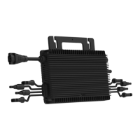
The microinverters are built for high reliability, featuring an IP67 (NEMA 6) enclosure, which provides protection against dust and water ingress, and 6000 V surge protection. They are designed for natural convection cooling, meaning they have no fans, which contributes to their durability and silent operation.
Installation involves marking the position of each microinverter on the rail according to the PV module layout, fixing screws on the rail, and then hanging and tightening the microinverter. The silver cover side of the microinverter should face the panel. It is crucial to install the microinverter underneath the PV modules to ensure it works in the shade and to avoid direct sunlight, which can cause power derating due to increased internal temperature. A minimum of 2 cm of space around the microinverter enclosure should be maintained for ventilation and heat dissipation.
The AC Trunk Cable is used to connect the microinverter to the power distribution box. The installation process includes disassembling the AC Trunk Connector, installing an AC Trunk End Cap on one side, and installing an AC end cable on the other side for connection to the distribution box. Proper stripping requirements for the AC cable must be fulfilled, and the L, N, and PE wires must be inserted into their corresponding slots. The AC Trunk Cable should be attached to the mounting rail and secured with tie wraps.
After physical installation, the AC Sub Connector of the microinverter is plugged into the AC Trunk Connector until a click is heard. The AC end cable is then connected to the local grid network. It is important to peel the serial number label from each microinverter and affix it to the respective location on the installation map for record-keeping. Finally, the PV modules' DC cables are connected to the DC input side of the microinverter. The system is energized by turning on the AC breaker of the branch circuit and then the main AC breaker of the house.
The microinverter is compatible with Hoymiles gateway DTU-Pro-S and DTU-Lite-S for monitoring. Users should refer to the "DTU User Manual," "DTU Quick Installation Guide," and "Quick Installation Guide for S-Miles Cloud" to install the DTU and set up the monitoring system.
Maintenance Features
Routine maintenance of the Hoymiles microinverter system is crucial for optimal performance and longevity. Only authorized and trained personnel should carry out maintenance operations. Personal protective equipment, such as gloves and goggles, must be used during installation and maintenance.
Regular checks of the environmental conditions are recommended to ensure they remain suitable for the microinverter's operation, including adequate ventilation and protection from adverse weather. The equipment should not be used if any operating anomalies are detected, and any issues should be resolved before resuming operation.
Annual inspections of various components are advised, along with cleaning the equipment using a vacuum cleaner or special brushes. It is important to avoid cleaning the equipment with filamentary or corrosive materials to prevent corrosion and electrostatic charges.
Troubleshooting a malfunctioning microinverter involves several steps:
- Verify that the utility voltage and frequency are within the specified range in the Technical Data section.
- Check the connection to the utility grid. When de-energizing, disconnect AC power first, then DC power. When re-connecting, connect PV modules first, then AC power. The LED indicator provides visual feedback on connection status (red for DC connection, green for normal DC and AC connection).
- Confirm the interconnection between all microinverters on the AC branch circuit and ensure each inverter is energized by the utility grid.
- Verify that all AC breakers are functioning correctly and are closed.
- Check the DC connection between the microinverter and the PV module.
- Ensure that the PV modules' DC voltage is within the allowable range specified in the Technical Data section.
- If problems persist, contact Hoymiles customer support.
It is strictly forbidden to attempt to repair the microinverter by oneself, as there are no user-serviceable parts inside for safety and insulation reasons. If troubleshooting fails, the microinverter should be returned to the factory for replacement. The AC output wiring harness cannot be replaced; if damaged, the equipment must be scrapped. Maintenance operations must be performed with the equipment disconnected from the grid and PV modules shaded or isolated.
For decommissioning, the inverter should be disconnected from DC input and AC output, all connection cables removed, and the microinverter detached from the frame. It should be packed in its original packaging or a suitable carton box for storage or transportation. The storage temperature range is -40 to 85°C. When restarting after a long period of storage, a complete inspection is necessary. Disposal of microinverters must be done in accordance with local regulations to prevent environmental harm.