EasyManua.ls Logo

Hoymiles HMS-1800-4T-NA User Manual

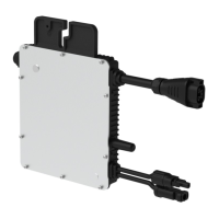
Hoymiles HMS-1800-4T-NA
30 pages
To Next Page IconTo Next Page
Page #1 background imageLoading...
Page #1 background image
Open Energy for All
Single-phase Microinverter
HMS-1600-4T-NA
HMS-1800-4T-NA
HMS-2000-4T-NA
USER MANUAL
Region: North America V202201 hoymiles.com

Other manuals for Hoymiles HMS-1800-4T-NA

Questions and Answers:

Hoymiles HMS-1800-4T-NA Specifications

General IconGeneral
ModelHMS-1800-4T-NA
CategoryInverter
Rated Output Power1800W
Rated AC Output Power1800W
Recommended Input Power (STC)2400W
Number of MPPTs4
Number of MPPT Trackers4
Output Power1800W
Nominal Output Voltage240V
AC Output Voltage240V
Nominal Output Frequency60Hz
AC Output Frequency60Hz
Maximum Output Current7.5A
Power Factor>0.99
Total Harmonic Distortion (THD)<3%
Max Efficiency96.7%
Efficiency CEC96.5%
Efficiency96.7%
Ambient Temperature Range-40°C to +60°C
Operating Temperature Range-40°C to +60°C
Dimensions280 mm × 240 mm × 37.6 mm
Weight3.5kg
Cooling MethodNatural Convection
Input Voltage Range16V-60V
Peak Power Tracking Voltage Range36V-48V
MPPT Voltage Range36V-48V

Summary

About Microinverter

About Safety

2.1 Important Safety Instructions

Precautions for installation, operation, and maintenance by qualified personnel.

2.2 Explanation of Symbols

Explains symbols like waste disposal, caution, high voltage, hot surface, CE, FCC, read manual.

About Product

3.2 About Microinverter

Module-level solar inverter tracking MPPT, safety, monitoring.

Installation Preparation

4.1 Position and Space Required

Guidance on microinverter placement for optimal performance and ventilation.

4.2 Connecting Multiple PV Modules to Microinverter

General guidelines and wiring methods for connecting PV modules.

4.5 Precautions

Essential precautions for installation, environment, and location.

Microinverter Installation

Step 1. Plan and Install the Microinverter

Instructions for marking positions, fixing screws, and mounting the microinverter.

Step 2. Plan and Build the AC Trunk Cable

Guidance on selecting, preparing, and laying out AC trunk cables.

Step 3. Complete the AC Connection

Steps to connect microinverter to AC trunk connector and distribution box.

Troubleshooting

6.1 Troubleshooting List

Lists common alarm codes, status, and handling suggestions for various issues.

6.2 LED Indicator Status

Explains the meaning of different LED flash patterns during startup and operation.

6.3 On-site Inspection (For qualified installer only)

Step-by-step guide for inspecting a malfunctioning microinverter.

6.5 Microinverter Replacement

Procedures for removing and replacing a microinverter and updating the monitoring platform.

Technical Data

Grid Support Details

Related product manuals