HMS-1000W-2T Series Microinverter Quick Installation Guide
Region: Europe REV1.1 AP040873 ©2023 Hoymiles Power Electronics Inc. 01
Check the Parts and Tools
1
1
2
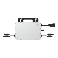
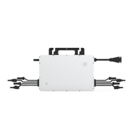
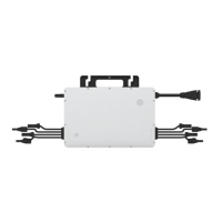
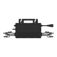
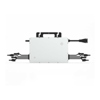
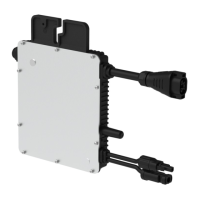
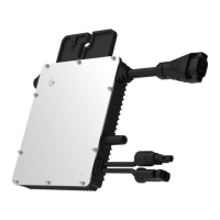
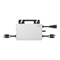
Microinverter
Guide & Map
S-Miles Installer
Preparation
0
Product Application
Download the Application
3
Plan the Microinverters
For a single-microinverter system, the entire system consists of one
microinverter and two PV modules.
For a multi-microinverter system, define the number of microinverters
per AC output line based on the capacity of the AC cables.
HMS-600W-2T
9
HMS-700W-2T
7
HMS-800W-2T
6
2.5 mm²
Model
6
HMS-900W-2T
5
HMS-1000W-2T
Multi-Microinverter System—Maximum Microinverter Numbers per Line (230 V)
Warning:
AC cable ampacity determines the limits, which may vary. Check local codes for the actual limitations.
Wire
Stripper
Torque
Wrench
Crimping
Tool
HMS Disconnect
Tool
Diagonal
Cutter
M8 Screws
PPE
Electrical Drill
Cable Tie
Tools Required
Scope of Deliver
Download the S-Miles Installer Application. To download,
•
Scan the QR code located on the right side.
• Search for “Hoymiles Installer” on App Store or Google Play.
Read this guide thoroughly before installation.
Operation personnel must wear proper personal protective equipment (PPE).
Avoid working with live wires. Ensure that AC and DC wires are not charged
before any connection work.
Adhere to the applicable codes and regulations of the installation site.
Hoymiles is not liable for damages resulting from improper installation and use.
This installation must be carried out with all devices from the grid.
To avoid damaging the microinverter or potential fire hazards, ensure all terminals
are securely tightened with the correct torque when connecting AC and DC cables.
Single-phase, 230 V, with Neutral
HMS-1000W series microinverter can be operated on the following grids:
Microinverter
HMS Cable
System
Rooftop-Multi-Microinverter System
HMS Plug and
Play Cable
Microinverter
Balcony-Single-Microinverter System
AC Cable
HMS Cable
Connector
HMS Trunk
Connector
HMS Sealing
Cap
HMS Connection
Cable
HMS Extension
Connector
(optional)
Parts Required
HMS Field
Connector
AC Cable
or
Plug and Play
Body
a. Plan and mark the position of microinverter.
b. Drill holes with an electrical drill.
2
Mechanical Installing
a. Position the Microinverter
a. Mount and align the microinverter (label side up) with the drilling holes.
b. Fix the microinverter with screws (Torque: 9 N·m).
b. Fix the Microinverter
Single-
Micro-
inverter
System
Multi-
Micro-
inverter
System
Three-phase, 230 V / 400 V, with Neutral
The HMS-1000W series can be used in both single-microinverter and multi-microinverter systems.
•
A single-microinverter system is a solar power setup with one microinverter and two PV modules, designed for installation on a balcony or an outdoor area.
•
A multi-microinverter system consists of multiple microinverters, each microinverter is paired with two PV modules, providing optimized performance.
Method One - Single-Microinverter System
Mounting Torque : 9 N·m
Label Side
Warning:
Factors to consider:
• Handrail should be structurally stable and can support the microinverter’s weight.
• Avoid uneven, slanted, or rough surfaces.
-40℃
to
65℃
Warning:
Given the complexity of balcony installations, consider handrail stability, weight limitations, appropriate mounting
methods, and compliance with balcony regulations, and seek professional advice if necessary.
*
* Choose the correct
installation tools
based on site
conditions, as tools for
balcony systems and
rooftop systems differ.