This document describes the Hoymiles HMT-1600-4T/HMT-1800-4T/HMT-2000-4T three-phase microinverter, a key component in grid-tied PV inverter systems. This system is designed to convert direct current (DC) from photovoltaic (PV) modules into alternating current (AC) suitable for feeding into the public grid.
Function Description
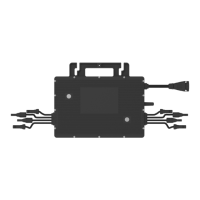
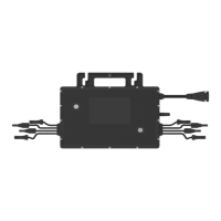
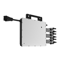
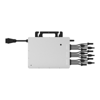
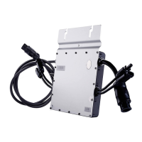
The microinverter system is composed of multiple microinverters, each designed as a 4-in-1 unit, meaning one microinverter connects to four PV modules. This architecture allows each microinverter to operate independently, ensuring maximum power generation from each individual PV module. This independent operation enhances system flexibility and reliability by enabling direct control and optimization of each PV module's production.
The HMT-2000-4T series microinverters incorporate Maximum Power Point Tracking (MPPT) at the module level. This technology continuously tracks the maximum DC power point of each PV module, optimizing energy harvest. The dual MPPT design further enhances performance, particularly in scenarios with partial shading. If one MPPT experiences shading or failure, the other MPPT can continue to operate the unshaded string at its maximum efficiency point, ensuring consistent optimal performance.
A significant safety feature of the HMT-2000-4T microinverter is its low DC voltage operation, typically carrying only a few dozen volts. This significantly reduces potential safety hazards compared to traditional string inverter systems that operate at much higher DC voltages.
The microinverter system also includes module-level monitoring capabilities. It wirelessly collects data from each microinverter and transmits it to the Hoymiles monitoring platform, S-Miles Cloud. This allows users to monitor the performance of individual modules and the overall system via a web interface or a mobile application.
Usage Features
The HMT-2000-4T series microinverters are designed for commercial and industrial applications, offering a three-phase output. With output power up to 2000 VA, these microinverters are compatible with 182 mm/210 mm PV modules.
Installation is streamlined due to the 4-in-1 design, which contributes to faster setup and potentially lower costs. The microinverter integrates a grid protection relay, ensuring safe and compliant operation with the public grid.
For communication, the microinverter utilizes Sub-1G wireless technology. This solution provides more stable communication with the Hoymiles gateway DTU compared to 2.4GHz bands like Wi-Fi or Zigbee. Sub-1G operates on the 868 MHz or 915 MHz band, offering a substantially longer range (1.5 to 2 times greater) and superior interference suppression performance, which is particularly beneficial in industrial and commercial PV power plants. Additionally, Sub-1G wireless communication consumes less power, making it well-suited for rooftop PV power stations.
The microinverter is designed for safety, complying with rapid shutdown requirements and featuring an isolated transformer, making it safer for rooftop solar installations.
When installing, it is crucial to position the microinverter and all DC connections underneath the PV module to protect them from direct sunlight, rain, snow buildup, and UV exposure. The silver side of the microinverter should face upwards, towards the PV module. A minimum clearance of 2 cm around the microinverter enclosure is required to ensure adequate ventilation and heat dissipation.
Connecting multiple PV modules to the microinverter involves connecting PV modules to the DC input ports. If the original cables are not long enough, DC extension cables can be used, provided they comply with local regulations. It is essential to ensure that the voltage of the modules, considering local temperature effects, does not exceed the microinverter's maximum input voltage to prevent damage.
The AC connection process involves plugging the AC Sub Connector of the microinverter into the 3P-AC Trunk Connector until a "click" is heard. The AC end cable is then connected to the distribution box and wired to the local grid network. Any vacant AC Trunk Ports must be sealed with a 3P-AC Trunk Port Cap to ensure water and dust protection.
After installation, an installation map should be created by affixing the removable serial number labels from each microinverter to their respective locations on the map. PV modules are then mounted above the microinverters, and their DC cables are connected to the microinverter's DC input side.
To energize the system, first turn on the AC breaker of the branch circuit, then the main AC breaker of the house. The system will typically begin generating power within two minutes. A monitoring system can then be set up using the DTU (Data Transfer Unit) and the S-Miles Cloud platform, following the provided user manuals and quick installation guides.
Maintenance Features
Routine maintenance of the microinverter system should only be performed by authorized personnel. Personal protective equipment, such as gloves and goggles, must be used during all maintenance operations.
Regular checks of environmental conditions are necessary to ensure they remain within specified limits and that the equipment is not obstructed or exposed to adverse weather. If any operating anomalies are detected, the equipment should not be used until the fault is fixed and working conditions are restored.
Annual inspections of various components are recommended, along with cleaning the equipment using a vacuum cleaner or special brushes. It is strictly forbidden to clean the equipment with rags made of filamentary or corrosive materials to prevent corrosion and electrostatic charges.
Troubleshooting guidance is provided through an LED indicator status on the microinverter. During start-up, five green flashes (0.3s gap) indicate success, while five red flashes (0.3s gap) indicate failure. Fast red flashes (0.2s gap) signal an improperly connected neutral wire. During operation, fast green flashes (1s gap) indicate power production, and slow green flashes (2s gap) suggest power production with one abnormal input. Red flashes (0.5s gap) indicate an invalid AC grid or hardware failure, while red flashes (1s gap) signify no power production due to an invalid AC grid. A solid red light indicates hardware failure. Alternating red and green flashes mean the firmware is broken. All faults are reported to the DTU and the Hoymiles Monitoring Platform for detailed information.
On-site inspection by qualified installers involves verifying that the utility voltage and frequency are within the specified range, checking the connection to the utility grid, and ensuring all AC breakers are functioning correctly and closed. DC connections between the microinverter and PV modules should also be checked, confirming that PV module DC voltage is within the allowable range.
In case of microinverter replacement, the AC branch circuit breaker must be de-energized, and the PV module removed and covered. An electric meter should be used to confirm no current flow in the DC wires. DC and AC connectors are then removed using appropriate tools. The microinverter's fixing screws are loosened, and the unit is removed from the PV racking. A new microinverter is installed following the installation steps, ensuring the new unit's serial number is noted. The monitoring platform is then updated by accessing the "Device List," selecting the replaced device, and using the "Replace Device" function to input the new serial number.
The microinverter is designed for durability with an outdoor-IP67 enclosure rating and natural convection cooling (no fans). Its storage temperature range is -40°C to 85°C.
For decommissioning, the inverter must be disconnected from DC input and AC output, all connection cables removed, and the microinverter detached from its frame. It should be packed in its original packaging or a suitable carton box for transport. Hoymiles packaging is designed to protect components from violent shocks, humidity, and vibration during transportation. Any damage or missing parts upon receipt should be reported immediately to the carrier or authorized distributor.
If the equipment is not used immediately or stored for a long period, it must be properly packed and stored indoors with good ventilation, free from potential damage. A complete inspection is required before restarting equipment that has been out of operation for an extended time. Finally, microinverters must be disposed of properly in accordance with local regulations to prevent environmental harm.