Do you have a question about the HP 1810-24 and is the answer not in the manual?
Use Phillips screwdriver and M4 screws to attach brackets to switch, then use 12-24 screws to secure to rack.
Attach four self-adhesive pads to the bottom corners of the switch for table or desktop placement.
Mount switch using screws into surface, sliding to lock. Use third screw to prevent sliding.
Reconfigure PC IP/Subnet, access switch web interface, log on, and set network configuration.
Use only genuine HP transceivers. Ensure fiber SFP operates within temperature limits.
Warnings and cautions for securing racks, wall mounting, power sources, and environment.
| Switching Capacity | 48 Gbps |
|---|---|
| Forwarding Rate | 35.7 Mpps |
| Layer | Layer 2 |
| Jumbo Frame Support | Up to 9216 Bytes |
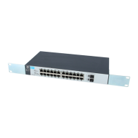
| Mounting | Rack-mountable |
| Additional Ports | 4 x SFP |
| MAC Address Table Size | 8192 entries |
| Management | Web interface |
| Operating Temperature | 0 to 50 °C |
| Operating Humidity | 10% to 90% non-condensing |
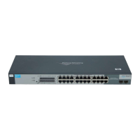
| Ports | 24 x 10/100/1000 RJ-45 auto-negotiating ports 2 x 100/1000 SFP ports |