1-4
Introducing the Switch
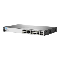
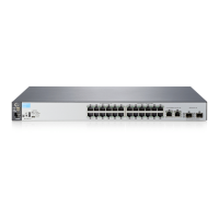
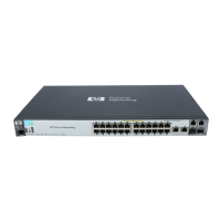
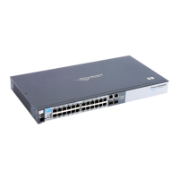
Front of the Switch
Introducing the Switch
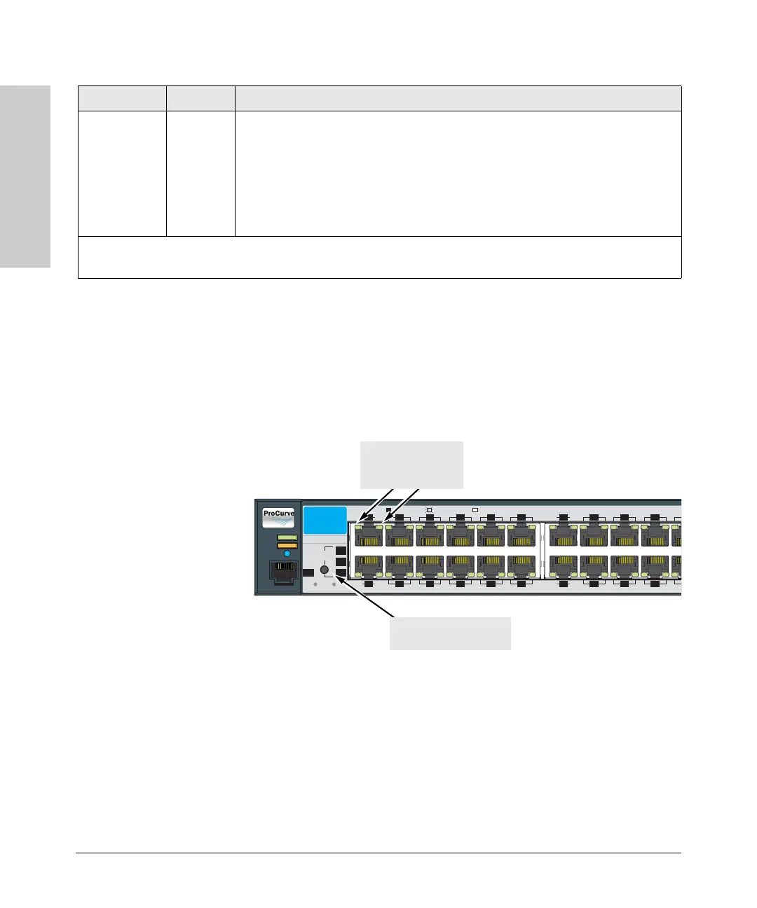
LED Mode Select Button and Indicator LEDs
To optimize the amount of information displayed for each of the switch ports
without overwhelming you with LEDs, the Series 2510 Switch uses two LEDs
for each port. The operation of these LEDs is controlled by the LED Mode
select button, and the current setting is indicated by the LED Mode indicator
LEDs near the button. Press the button to step from one view mode to the next.
■ Each port has a Link LED. If it is lit, the port has a link. If the Link LED is
blinking, the port has failed its self test. The Fault and Test LEDs will be
blinking simultaneously.
■ If the Activity (Act) indicator LED is lit, each port LED displays activity
information for the associated port—it flickers as network traffic is
received and transmitted through the port.
LED Mode
View (3 green
LEDs)
Act Indicates the port LEDs are displaying network activity information.
FDx Indicates port LEDs are lit for ports in Full Duplex Mode. Off indicates half duplex.
Spd Indicates port Mode LEDs are displaying the connection speed of each port.
• if the port LED is off, the port is operating at 10 Mbps.
• if the port LED is blinking **, the port is operating at 100 Mbps.
• if the port LED is on continously, the port is operating at 1000 Mbps.
* The blinking behavior is an on/off cycle once every 1.6 seconds, approximately.
** The blinking behavior is an on/off cycle once every 0.8 seconds, approximately.
Switch LEDs State Meaning
Power
Fault
Locator
Console
10/100Base-T Ports (1 - 24) Ports are HP Auto MDI-X
*
Spd mode: off = 10 Mbps, flash = 100 Mbps, on = 1000 Mbps
12
10
864
2
11
97
5
3
1
Link
Mode
Link
Mode
2018
16
14
19
17
15
13
Link
Mode
Link
Mode
LED
Mode
Clear
Reset
Test
FDx
Spd
Act
*
ProCurve Switch
2510-24
J9019A
ProCurve Switch 2510-24
Port LEDs
(two for each port)
Link and Mode
LED Mode select button
and indicator LEDs
 Loading...