EasyManua.ls Logo

HP 280 G2 MT Business - User Manual

HP 280 G2 MT Business
13 pages
Print Icon
To Next Page IconTo Next Page
Loading...
EL-MF877-00 Page 1
Template Revision B
PSG instructions for this template are available at EL-MF877-01
Product End-of-Life Disassembly Instructions
Product Category: Personal Computers
Marketing Name / Model
[List multiple models if applicable.]
HP 280 G2 MT Business PC
Purpose: The document is intended for use by end-of-life recyclers or treatment facilities. It provides the basic instructions
for the disassembly of HP products to remove components and materials requiring selective treatment, as defined by EU
directive 2002/96/EC, Waste Electrical and Electronic Equipment (WEEE).
1.0Items Requiring Selective Treatment
1.1 Items listed below are classified as requiring selective treatment.
1.2 Enter the quantity of items contained within the product which require selective treatment in the right column, as
applicable.
Item Description Notes
Quantity
of items
included
in product
Printed Circuit Boards (PCB) or Printed Circuit
Assemblies (PCA)
With a surface greater than 10 sqcm
MB, Memory,HDD PCA,ODD PCA,PSU PCA
5
Batteries
All types including standard alkaline and lithium
coin or button style batteriesMB
1
Mercury-containing components
For example, mercury in lamps, display backlights,
scanner lamps, switches, batteries
0
Liquid Crystal Displays (LCD) with a surface
greater than 100 sq cm
Includes background illuminated displays with gas
discharge lamps
0
Cathode Ray Tubes (CRT)
0
Capacitors / condensers (Containing PCB/PCT)
0
Electrolytic Capacitors / Condensers measuring
greater than 2.5 cm in diameter or height
PSU
2
External electrical cables and cords
Power cord
1
Gas Discharge Lamps
0
Plastics containing Brominated Flame
Retardantsweighing > 25 grams (not including
PCBs or PCAs already listed as a separate item
above)
system fan, Cooler fan,PSU fan
3
Components and parts containing toner and ink,
including liquids, semi-liquids (gel/paste) and toner
Include the cartridges, print heads, tubes, vent
chambers, and service stations.
0
Components and waste containing asbestos
0
Question and Answer IconNeed help?

Do you have a question about the HP 280 G2 MT Business and is the answer not in the manual?

Summary

Items Requiring Selective Treatment

Tools Required

Product Disassembly Process

Remove Access Panel

Release screw on the access panel, grip the tab, pull towards the rear and remove.

Remove Front Panel

Release 3 bezellatches from chassis by pulling the bezellatches outwards.

Remove Cables

Disconnect and remove all cables from the unit.

Remove Hard Disk Drive (HDD)

Remove the HDD from the unit using indicated release points.

Remove Optical Disk Drive (ODD)

Remove the ODD from the unit using indicated release points.

Remove Power Supply Unit (PSU)

Take off the PSU from the unit by releasing retaining screws.

Remove System Fan

Take off the system fan from the unit by releasing retaining screws.

Remove Card Reader

Take off the Card Reader from the unit by releasing retaining screws.

Remove Front I;O (FIO)

Take off the FIO from the unit by releasing retaining screws.

Remove Memory

Release memory socket levers by pulling outward.

Remove CPU Cooler

Rotate the screw driver to release CPU cooler from the unit.

Remove PCA (Printed Circuit Assembly)

Rotate screw driver to loose PCA from the unit.

Remove Battery

Take off the battery from the unit.

Open PSU and Remove Fan

Open the PSU cover and take off the PSU fan.

Remove PCA from PSU

Rotate the screw driver to release the PCA from PSU.

Remove CAP using Electric Iron

Use an electric iron to remove the CAP.

Overview

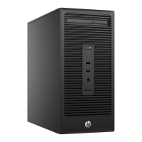
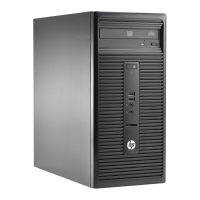
This document outlines the disassembly instructions for the HP 280 G2 MT Business PC, a personal computer, intended for end-of-life recyclers and treatment facilities. Its primary function is to guide the removal of components and materials requiring selective treatment, as defined by EU directive 2002/96/EC (Waste Electrical and Electronic Equipment - WEEE).

Important Technical Specifications and Components Requiring Selective Treatment:

The device contains several components that require selective treatment during disassembly. These include:

  • Printed Circuit Boards (PCB) or Printed Circuit Assemblies (PCA): The PC contains 5 such assemblies, each with a surface area greater than 10 sqcm. These include the Motherboard (MB), Memory, Hard Disk Drive (HDD) PCA, Optical Disk Drive (ODD) PCA, and Power Supply Unit (PSU) PCA.
  • Batteries: The device includes 1 battery, which can be any type, including standard alkaline, lithium coin, or button-style batteries, specifically found on the motherboard.
  • Capacitors / Condensers (Electrolytic): There are 2 electrolytic capacitors/condensers in the Power Supply Unit (PSU) that measure greater than 2.5 cm in diameter or height.
  • External Electrical Cables and Cords: The device includes 1 power cord.
  • Plastics containing Brominated Flame Retardants: There are 3 plastic components weighing over 25 grams (excluding PCBs or PCAs) that contain brominated flame retardants. These are identified as the system fan, cooler fan, and PSU fan.

The device does not contain the following materials that would otherwise require selective treatment:

  • Mercury-containing components (e.g., in lamps, display backlights, scanner lamps, switches).
  • Liquid Crystal Displays (LCD) with a surface greater than 100 sq cm (including background illuminated displays with gas discharge lamps).
  • Cathode Ray Tubes (CRT).
  • Capacitors / condensers containing PCB/PCT.
  • Gas Discharge Lamps.
  • Components and parts containing toner and ink (including liquids, semi-liquids, gel/paste, cartridges, print heads, tubes, vent chambers, service stations).
  • Components and waste containing asbestos.
  • Components, parts, and materials containing refractory ceramic fibers.
  • Components, parts, and materials containing radioactive substances.

Usage Features (Disassembly Process):

The disassembly process is structured into a series of sequential steps, designed to facilitate the removal of selectively treated components. The process requires specific tools and a methodical approach:

Tools Required:

  • Crisscross screw driver: Size 2#
  • Hexagon screw driver: Size T15
  • Electric iron: Model QUICK 310 (used for capacitor removal)

Disassembly Steps:

  1. Remove access panel from the unit: This involves releasing a screw on the access panel, gripping a tab at the end of the panel, pulling it towards the rear, and then removing it from the unit.
  2. Remove front panel from the unit: Release 3 bezel latches from the chassis by pulling them outwards.
  3. Remove all cables from the unit: Disconnect all internal cables.
  4. Remove HDD from the unit: Detach the hard disk drive.
  5. Remove ODD from the unit: Detach the optical disk drive.
  6. Take off PSU from the unit: Rotate a screwdriver to release the PSU from the unit.
  7. Take off the system fan from the unit: Rotate a screwdriver to loosen the screw and remove the system fan.
  8. Take off Card Reader from the unit: Remove the card reader.
  9. Take off FIO (Front Input/Output) from the unit: Remove the FIO module.
  10. Take off Memory from the unit: Release the memory socket levers by pulling them outward, then remove the memory modules.
  11. Take off CPU cooler from the unit: Rotate a screwdriver to release the CPU cooler from the unit.
  12. Take off PCA (Printed Circuit Assembly) from the unit: Rotate a screwdriver to loosen the PCA from the unit.
  13. Take off battery from the unit: Remove the motherboard battery.
  14. Open the PSU: Rotate a screwdriver to release the PSU cover.
  15. Take off PSU fan: Rotate a screwdriver and remove the PSU fan.
  16. Take off PCA from the PSU: Rotate a screwdriver to release the PCA from the PSU.
  17. Take off CAP (Capacitor) using electric iron: This step involves using an electric iron to safely remove capacitors from the PCA.

Maintenance Features (Implicit from Disassembly):

While not explicitly stated as "maintenance features," the detailed disassembly instructions provide a clear roadmap for accessing and replacing various internal components. This implies that:

  • Component Replacement: The step-by-step guide facilitates the replacement of components like the HDD, ODD, PSU, system fan, card reader, FIO, memory, CPU cooler, and even the motherboard (PCA) if necessary.
  • Battery Replacement: The specific instruction to "Take off battery from the unit" indicates that the motherboard battery is a user-replaceable component, likely for maintaining system time and BIOS settings.
  • Fan Cleaning/Replacement: The removal of the system fan and PSU fan suggests that these components can be accessed for cleaning to prevent overheating or for replacement if they fail.
  • Power Supply Servicing: The ability to open the PSU and remove its internal PCA and fan indicates that the power supply unit can be serviced, potentially for component-level repair or replacement of its internal parts.
  • Capacitor Repair: The instruction to "Take off CAP using electric iron" points to the possibility of repairing or replacing individual capacitors on the PSU's PCA, which is a common failure point in electronic devices.

The document emphasizes a structured approach to ensure that all hazardous or selectively treated materials are properly identified and removed, contributing to responsible end-of-life management of the HP 280 G2 MT Business PC.

HP 280 G2 MT Business Specifications

General IconGeneral
BrandHP
Model280 G2 MT Business
CategoryDesktop
LanguageEnglish

Related product manuals