TM 11-6625-1576-15
Section V
Paragraphs 5-10 to 5-11, Figure 5-2 and Table 5-2
setting.
Each decrease of the RANGE
switch represents 10 db fundamental re-
jection. Therefore, the total fundamental
rejection is the sum of the Wave Analyzer
reading and the 333A/334A indication.
k. The Distortion Analyzer METER RANGE setting
plus the Wave Analyzer RANGE setting plus the two
meter indications shall total more than -80 db.
5-10. SECOND HARMONIC ACCURACY CHECK.
a. Connect Test Oscillator (-hp-Model 651A) 600Ω
output to Distortion Analyzer *
b. Set Distortion Analyzer controls as follows:
FUNCTION Selector . . . . . . . SET LEVEL
FREQUENCY RANGE . . . . . . . . . . . X1
Frequency Dial . . . . . . . . . . . . . . .20
METER RANGE Selector . . . . . . . . . 0 DB
c. Set Test Oscillator controls (-hp- Model 651A)
as follows:
FREQUENCY RANGE . . . . . . . . . . . X10
FREQUENCY Dial. . . . . . . . . . . . . 2
OUTPUT ATTENUATOR . . . . . 1.0 VOLTS
AMPLITUDE . . . . . . . . . . . . . . l Volt
d. Adjust Distortion Analyzer SENSITIVITY con-
trols for a meter reading of O db.
e. Switch Distortion Analyzer FUNCTION selector
to DISTORTION. Adjust Frequency dial and BALANCE
controls for a null indication on meter.
f. Switch Distortion Analyzer FUNCTION selector
to SET LEVEL.
g. Adjust Test Oscillator frequency to 40 cps. Ad-
just AMPLITUDE control for a O db indication on the
Distortion Analyzer meter.
h. Switch Distortion Analyzer FUNCTION selector
to DISTORTION. The meter reading shall not change
more than ±0. 6 db.
Model 333A/334A
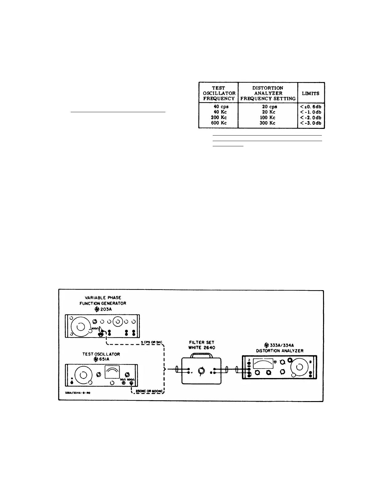
j. Repeat steps a through h at the frequency settings
indicated in Table 5-2.
The meter readings shall
change within the limits specified.
Table 5-2. Second Harmonic Accuracy Check
5-11.
a.
b.
c.
DISTORTION INTRODUCED BY INSTRUMENT
CHECK AND AUTOMATIC CONTROL LOOP
OPERATION.
Connect 333A/334A as shown in Figure 5-2.
Set Distortion Analyzer controls as follows:
FUNCTION Selector . . . . . . . SET LEVEL
SENSITIVITY Selector
. Position 1 step CCW
from Full CW position
SENSITIVITY VERNIER Control . . full CCW
METER RANGE Selector . . . . . . . . . . 0 db
FREQUENCY RANGE Selector . . . . . . . Xl
Frequency Dial . . . . . . . . . . . . . . .5
Set oscillator for approximately 1 volt output at
5 cycles.
d. Set filter box for 5 cycles.
e. Adjust oscillator amplitude for an indication of
+2 db on the Distortion Analyzer meter.
f. Switch Distortion Analyzer FUNCTION selector
to DISTORTION. Adjust frequency dial and BALANCE
controls for a null meter indication.
(If reading is in
lower 1/3 of meter scale, decrease METER RANGE
selector setting. )
g. The meter indication at “null” shall be at least
-8 db on the -60 db METER RANGE which is equiva-
lent to -70 db. Note reading.
Figure 5-2. Instrument Induced Distorition and Automatic Control Loop Test Setup
5-2
 Loading...


