Model 333A/334A
h. Set METER RANGE to O. 01 volt RANGE and off-
set frequency dial to a lower reading so that meter
cads full scale.
Set MODE switch to AUTOMATIC
id note distortion level. Distortion level should be
within +3 -O db of manually nulled reading.
j. Set MODE switch to MANUAL (and meter range
to o. 01).
Offset frequency dial past null to a higher
dial reading so that meter reads full scale. Return
MODE switch to automatic. Distortion reading should
be within +3 -O db of manually nulled reading obtained
in step g of this paragraph.
k. Set MODE switch to MANUAL and adjust fre -
quency dial for null.
Adjust COURSE BALANCE Con-
trol CW with METER RANGE set at 0. 01 so that meter
reads full scale. Return MODE Switch to AUTOMATIC.
Distortion reading should be within +3 -0 db of manually
nulled reading obtained in step g of this paragraph.
m. Set MODE switch to MANUAL and METER
RANGE to O. 01.
Adjust COARSE BALANCE Control
CCW so that meter reads +2 db. Set Mode switch to
Automatic. Distortion reading should be within +3 -O
of manually nulled reading obtained in step g of
this paragraph.
n. Repeat steps b through m with controls set as
indicated in Table 5-3. Except in steps j thru m use
METER RANGE setting of O. 03 to obtain +2 db reading
when detuning Frequency Dial and COARSE BALANCE
Control to verify automatic control loop operation.
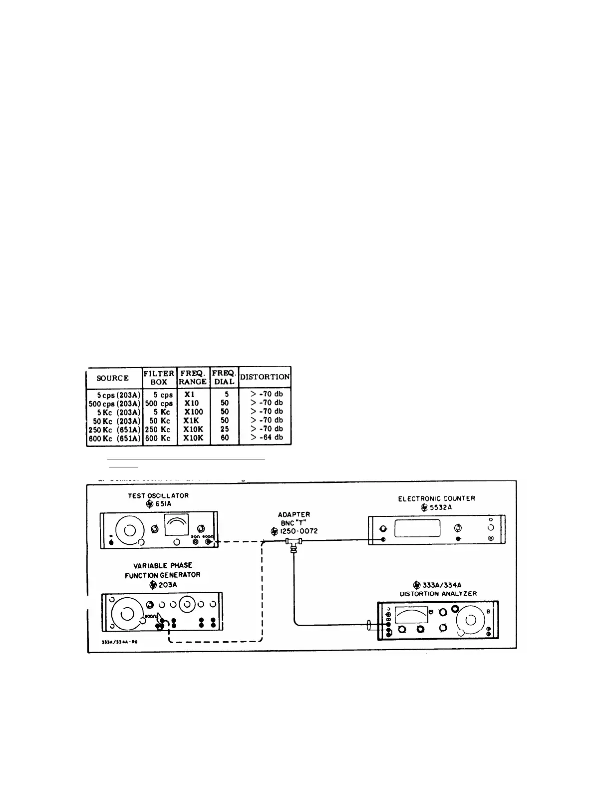
Table 5-3. Distortion Introduced By Instrument Check
5-12. FREQUENCY CALIBRATION ACCURACY
CHECK.
b.
c.
TM 11-6625-1576-15
Section V
Paragraph 5-12, Table 5-3, and Figure 5-3
NOTE
From 5 cps to 10 cps the FREQUENCY
dial may be as much as 3% low. In this
test the dial is held constant, and the in-
put frequency is varied and monitored.
If the dial is low, the input frequency at
null will be high.
If the period of the in-
put frequency is measured, it will be low
when the dial is low.
From 200 Kc to 600
Kc the dial may be as much as 8% high,
Consequently, a low frequency reading at
null would indicate that the dial is reading
high.
Set Distortion Analyzer controls as follows:
FUNCTION Selector . . . . . . . SET LEVEL
METER RANGE Selector . . . . . . . . 0 DB
SENSITIVITY Selector . . . . . . . . . . MIN.
FREQUENCY RANGE Selector . . . . . .Xl
Frequency Dial . . . . . . . . . . . . . . . .5
Set Test Oscillator controls (-hp- Model 203A)
as follows:
FREQUENCY RANGE . . . . . . . . . . . X1
FREQUENCY DIAL . . . . . . . . . . . . . . 5
OUTPUT ATTENUATOR . . . . . . 1.0 VOLT
d. Set Electronic Counter controls (-hp - Model
5532A) as follows:
SENSITIVITY . . . . . . . . . . 3 VOLTS RMS
Function Switch. . . . .
1 PERIOD AVERAGED
DISPLAY . . . . . . . . . . . . . . Fu1l CCW
e. Adjust Test Oscillator AMPLITUDE control for
a full scale indication on the Distortion Analyzer meter.
f. Switch Distortion Analyzer FUNCTION selector
to DISTORTION.
g. Adjust Test Oscillator FREQUENCY DIAL for
a null indication on the Distortion Analyzer meter.
(If reading is in lower 1/3 of meter scale, decrease
METER RANGE selector setting, )
h. Adjust Distortion Analyzer BALANCE controls
for a null indication on the meter. Repeat steps g and
a. Connect 333A/334A as shown in Figure 5-3.
Figure 5.-3. Test Setup for Frequency Calibration Accuracy Check
5-3
h until a null is reached.
 Loading...


