TM11-6625-1576-15
Section v
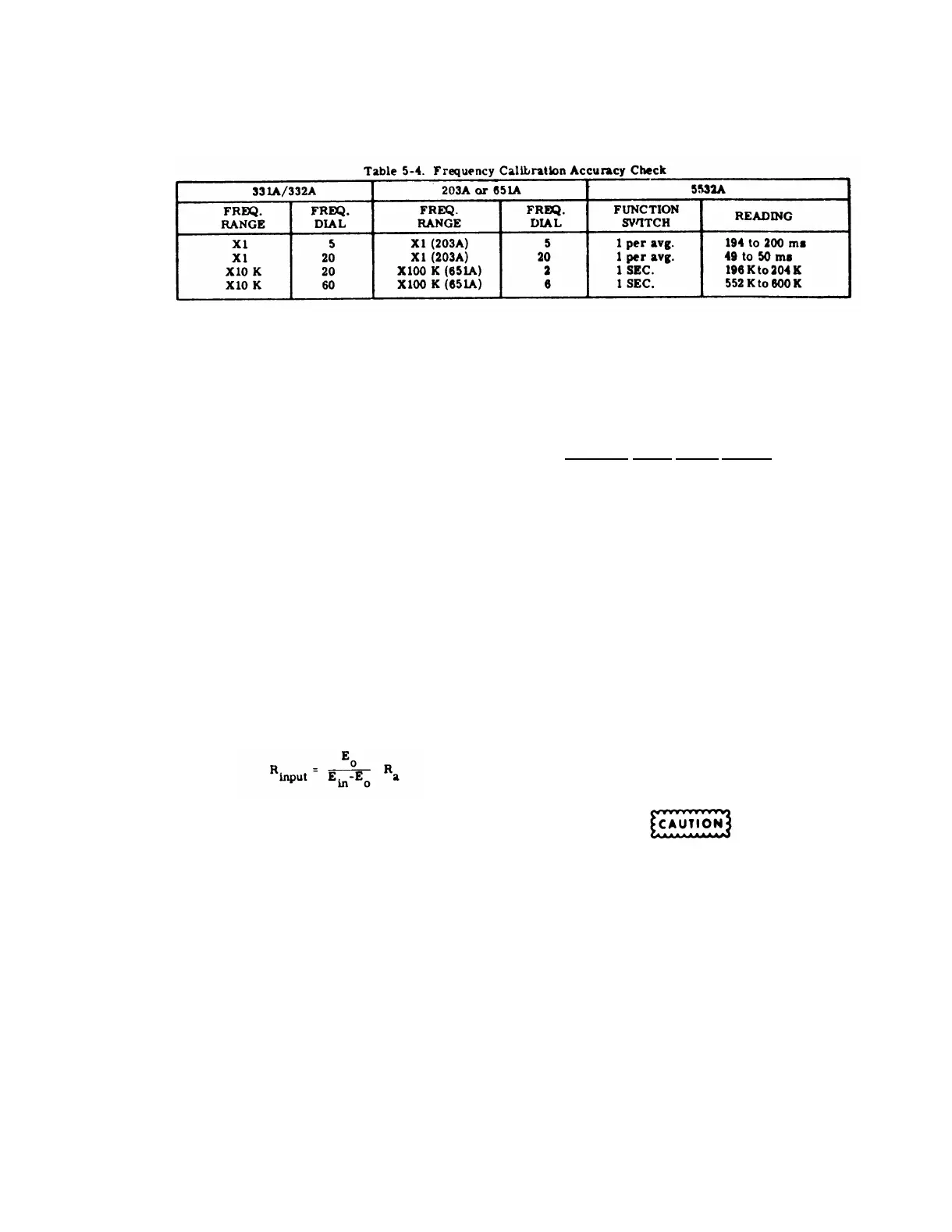
Paragraphs 5-13 to 5-16 and Table 5-4
Model 333A/334A
j. The Electronic Counter shall indicate the period
of 5 cps -3%, i. e. 194 to 200 msec.
k. Repeat steps b through h with controls set as
indicated in Table 5-4. The Electronic Counter shall
indicate the Test Oscillator output frequencies within
the limits indicated.
5-13. INPUT RESISTANCE CHECK
a. Connect Test Oscillator (-hp- Model 651A) 600
Ω output to Distortion Analyzer INPUT terminals.
b. Set Distortion Analyzer controls as follows:
FUNCTION Selector . . . . . . VOLTMETER
SENSITIVITY Selector . . . . . . . . . MAX.
SENSITIVITY VERNIER Control . . . . . MIN.
METER RANGE Selector. . . . . . . 1 VOLT
c. Set Test Oscillator controls as follows:
FREQUENCY RANGE . . . . . . . . . . X10
FREQUENCY Dial . . . . . . . . . . . . . 10
OUTPUT ATTENUATOR . . . . . . 1.0 VOLT
d. Adjust Test Oscillator AMPLITUDE control for
an indication of 1.0 volt (E
in
) rms on the Distortion
Analyzer meter.
e. Connect a 100 K
Ω (R
a
) ±1. 0%, 1/2 watt, fixed
carbon film resistor in series with the Distortion
Analyzer INPUT. Note the Distortion Analyzer meter
reading (E
o
).
f. Calculate the Distortion Analyzer input resis-
tance using the following formula:
g. The input resistance shall be 1 M
Ω ±5%.
h. Switch FUNCTION selector to Distortion and
calculate the input resistance in this position. It shall
be 1 M
Ω ±5%.
5-14.
a.
b.
INPUT SHUNT CAPACITANCE CHECK.
Set Distortion Analyzer controls as follows:
FUNCTION Selector . . . . . . . VOLTMETER
METER RANGE Selector . . . . . . . 1 VOLT
Connect an L - C meter to the 333A/334A and
measure the input capacitance.
c. The L - C meter shall indicate less than 30 pf.
d. Switch the Distortion Analyzer on the 0. 3 range
and measure capacitance. Meter shall indicate less
than 60 pf.
5-4
e. Set Distortion Analyzer controls as follows:
.
FUNCTION Selector . . . . . .DISTORTION
SENSITIVITY Selector . . . . . . . . . . MIN.
METER RANGE Selector . . . . . . . VOLTS
f. Measure Capacitance at each SENSITIVITY
selector setting of the Distortion Analyzer. The L - C
meter shall indicate less than 60 pf on each of these
settings.
5-15. MINIMUM INPUT LEVEL CHECK.
a. Connect Test Oscillator (-hp- Model 651A) 600
Ω output to Distortion Analyzer INPUT terminals l
Terminate test oscillator with
600
Ω ±1% 1/2 w resistor.
b.
c.
d.
Set Distortion Analyzer controls as follows:
FUNCTION Selector . . . . . . . VOLTMETER
METER RANGE Selector . . . . . . .3 VOLT
SENSITIVITY Selector . . . . . . . . . MIN.
SENSITIVITY VERNIER . . . . . . . . , CCW
Set Test Oscillator for 20 cps.
Adjust Test Oscillator amplitude for a Distortion
Analyzer
-
meter indication O. 3 volts.
e. Switch Distortion Analyzer FUNCTION selector
to SET LEVEL.
f. Switch SENSITIVITY selector to MAX and
VERNIER to full CW. The SENSITIVITY controls shall
have sufficient range to give a full scale meter reading.
5-16.
a.
b.
DC ISOLATION CHECK.
Connect 333A/334A as shown in Figure 5-4.
REMOVE SHORTING BARS BETWEEN
POWER LINE GROUND TERMINALS ON
DISTORTION ANALYZER INPUT TERMI-
NALS AND FUNCTION GENERATOR OUT-
PUT TERMINALS.
Set Distortion Analyzer controls as follows:
FUNCTION Selector . . . . . .VOLTMETER
METER RANGE Selector . . . . . . . 1 VOLT
c. Apply ac power to dc power supply and set for
400 v. Set Power SuppIy controls but do not apply dc
to the Distortion Analyzer.
d. Set Function Generator for 1 Kc and adjust the
amplitude control for an indication of 0. 9 on the Dis-
tortion Analyzer meter.
 Loading...


