d.
Keyboard (see
Keyboard on page 52)
e. Top cover (see
Top cover on page 55)
f.
Speakers (see
Speakers on page 64)
g. System board (see
System board on page 67)
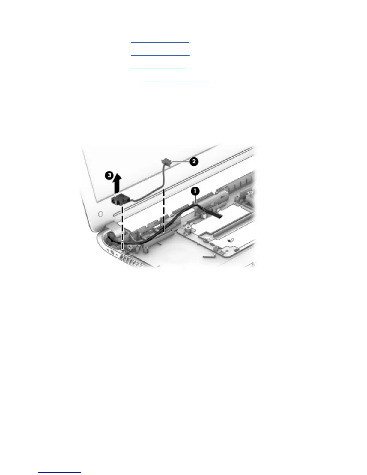
Remove the power connector cable:
1. Release the display panel cable (1) from the routing channel built into the base enclosure.
2. Release the power connector cable (2) from the routing channel built into the base enclosure.
3. Release the power connector (3) from the molding built into the base enclosure.
4. Remove the power connector cable.
Reverse this procedure to install the power connector cable.
Component replacement procedures
79
 Loading...