6.
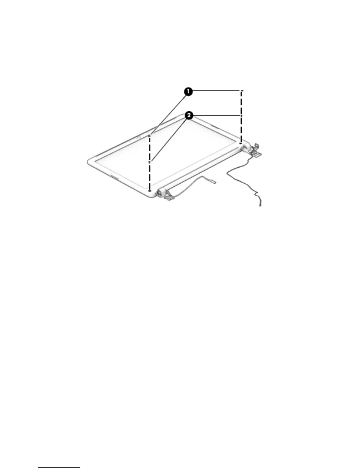
If it is necessary to replace the display bezel or any of the display assembly subcomponents:
a. Remove the two display bezel screw covers (1).
b. Remove the two Phillips PM2.0×3.75 screws (2) that secure the display bezel to the
display assembly.
c. Flex the inside edges of the top edge (1), the left and right sides (2), and the bottom
edge (3) of the display bezel until the bezel disengages from the display enclosure.
d.
Remove the display bezel (4).
The display bezel is available using the following spare part numbers:
●
753907-001–For use only on computer models equipped with
a webcamera in the United States
●
746661-001–For use only on computer models equipped with a webcamera in
countries/or regions other than the United States
●
753908-001–For use only on computer models not equipped with
a webcamera in the United States
●
746662-001–For use only on computer models not equipped with a webcamera in
countries/or regions other than the United States
82 Chapter 6 Removal and replacement procedures for Authorized Service Provider parts
 Loading...