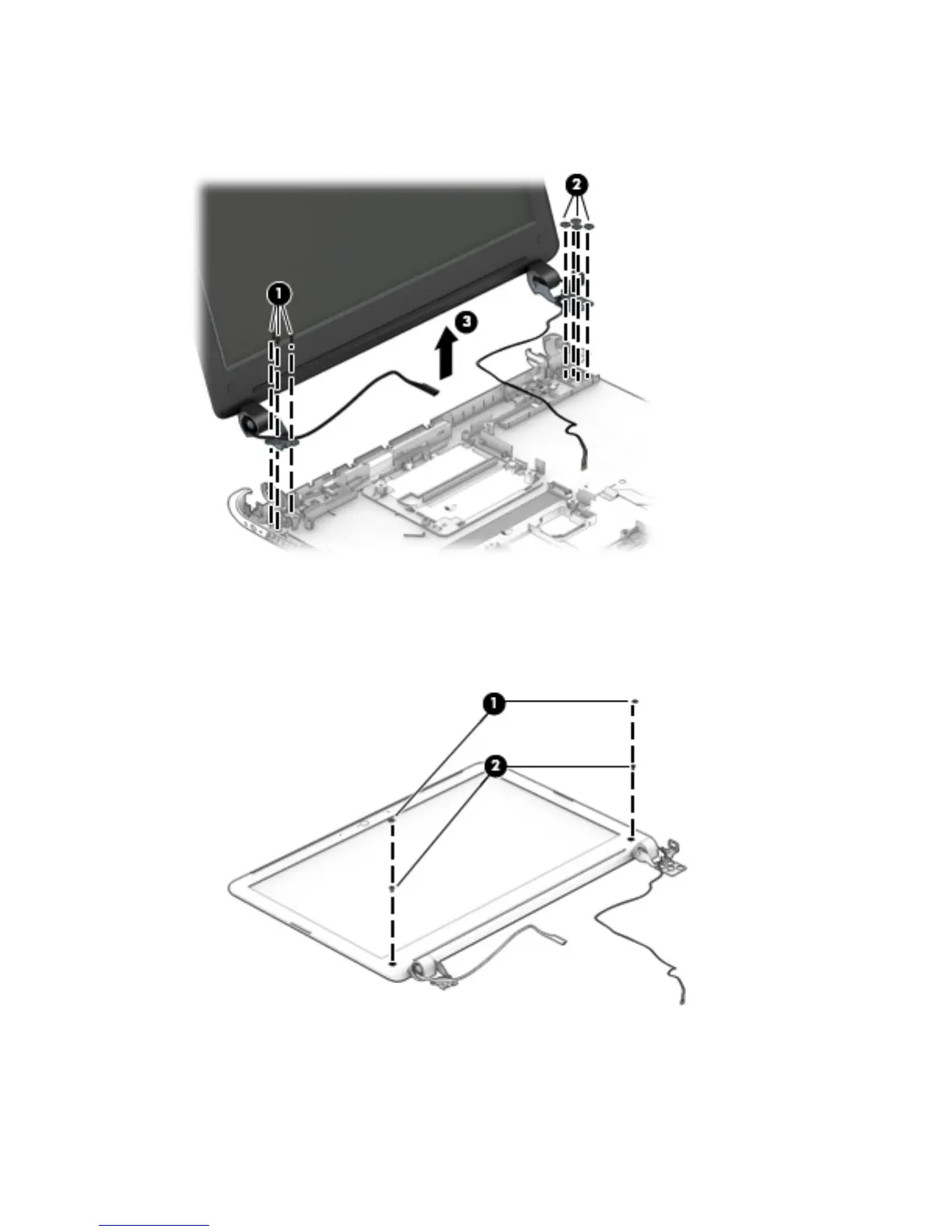
4. Remove the four Phillips PM2.5×3.25 broad head screws (2) that secure the display assembly right
hinge to the base enclosure.
5. Remove the display assembly (3).
6. If it is necessary to replace the display bezel or any of the display assembly subcomponents:
a. Remove the two display bezel screw covers (1).
b. Remove the two Phillips PM2.0×3.75 screws (2) that secure the display bezel to the
display assembly.
c. Flex the inside edges of the top edge (1), the left and right sides (2), and the bottom edge (3) of
the display bezel until the bezel disengages from the display enclosure.
d. Remove the display bezel (4).
The display bezel is available using the following spare part numbers:
64 Chapter 6 Removal and replacement procedures for Authorized Service Provider parts