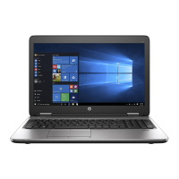
4. Remove the four Phillips PM2.5×3.25 broad head screws (2) that secure the display assembly right
hinge to the base enclosure.
5. Remove the display assembly (3).
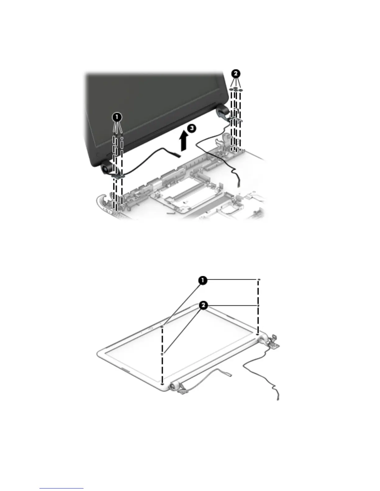
6. If it is necessary to replace the display bezel or any of the display assembly subcomponents:
a. Remove the two display bezel screw covers (1).
b. Remove the two Phillips PM2.0×3.75 screws (2) that secure the display bezel to the
display assembly.
Component replacement procedures 65
 Loading...