Model 35
75A
2,I.
INTRODUCTION.
2-2, This section
contairs informatioD
alld instructions
na:cssary for installing, shipping and
interfacing
the Model
3575A
Cain-Phase trleter. lncluded are initial
inspection
procedures,
power
and
grounding
requirements,
environ-
mental information,
mounting instructiol1s,
inslructions
for
repackaging
lor
shipment and interfacing
information
for
Option
001 arld
00-l instlumcnts.
2.3. INITIAL
INSPECTION.
24. This instrument
was carefully inspected
both nlechani
cally and
electrically before shipnrent.
It
should
be
physi-
cally
free of mars
or
scratchcs
and in
perfect electrical ordcr
upon receipt. To
confirm this, the instrument
should
bc
inspocted
for
physical damage incurred i[ transit.
lf the
instrurnent
was damaged in transit,
file
a clairn
with the
carrier. Check
for
supplied aocessorics
(Table
l'3) and test
the
electricai
pcrforrrrance
of the instrument
using the
performance
check
procedures
outiined in Section
V.
lf
there is
danage or
deficicncy.
sec
the warranty
oll
the
inside title
page of this
manual.
2.5.
POWER B EOUIREMENTS.
2-6. The ltlodel 3575A can
be operated
from any source
of
ll5
or
230
volrs
(1
l0%),
4t{ Hz to 440 Hz.
Power
dissipatiol is
50 VA: nlaximum.
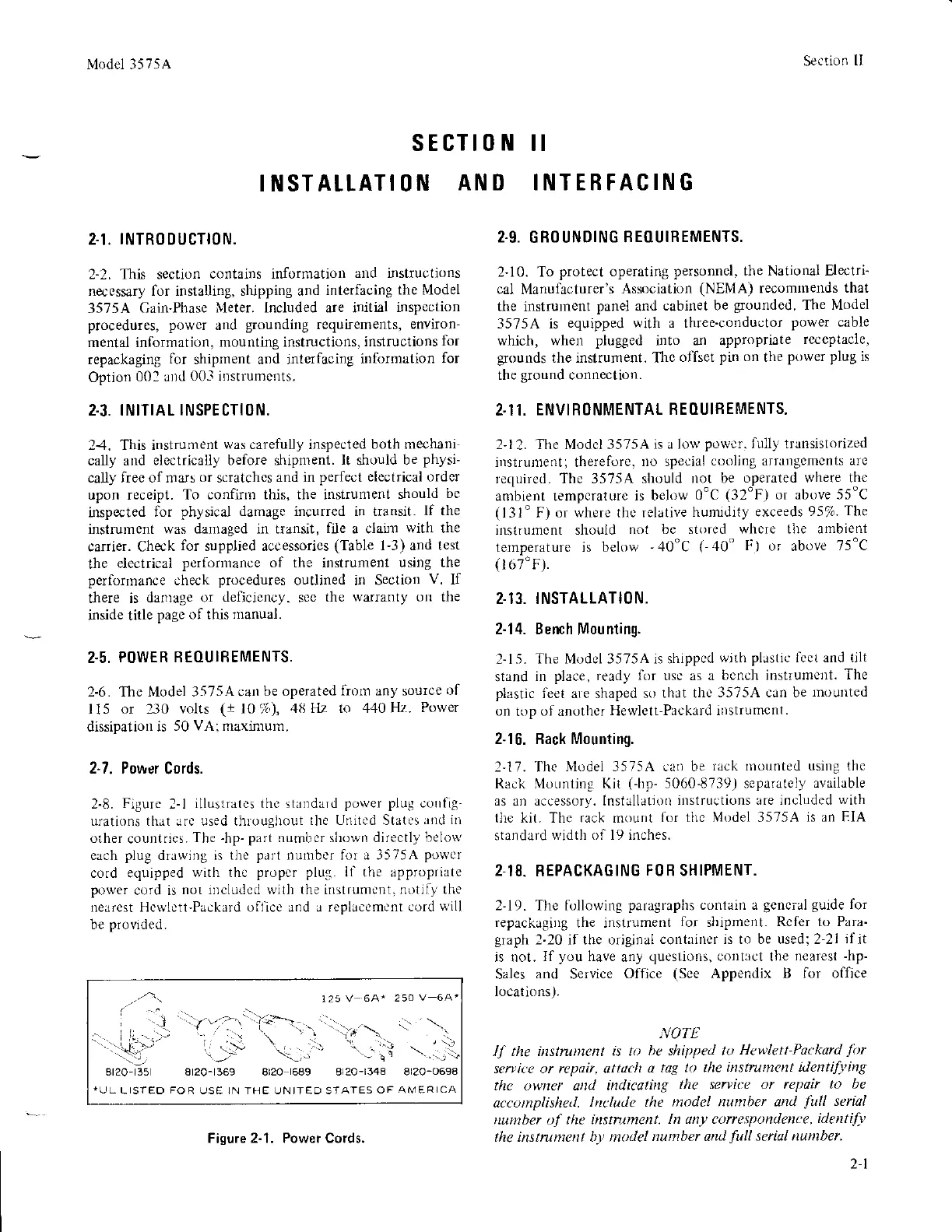
2-7. Power
Cords.
2-8.
Figure
2-l
illustritcs thc standard
power plug
cotrfig-
urations that lrc used throughout
lhe United Stxtc!
xnd ili
orher
countriqs.
The
-hp-
part
number shown directli,
below
each
plug
drawing is
tlie
part
numbcr foL a 3575A
powel
cord equipped
with thc
propcr plug.
ll the approprirte
power
cord is
not lncluded witlt the insttumcnt.
notlfl thr'
nearcst Hcwlctt-PilckaLd olllcc and a replacemcnt
cord
will
be
provided.
sEcTl0N il
INSTATLATION
AND INTEBFACING
Section
I
,.n:
-
125 V
64" 250
V 64'
ri
-,]
:ttr'7-1'':i-.,-,'',,a'.,.....
I
\,
..,,..,+,,1,
t
;j'i-".,,.,"
=r'..\
8t20- 35 8r20-t369 8t20
16A9
8120-1348 8120-0698
rUL
LISTEO
FOR
USE ]N THE UN ITEO SAATES
OF AMERICA
2.9.
GBO UNDING
BEOUIREMENTS.
2-10. To
protect operating
personncl. the National Electri-
cal Manufacturer's
Association
(NEMA)
recomrnends
that
the instrumcnt
panel
and
cabinet be
grounded.
The Nlodel
3575A is
equipped with a three-conductor
power
cable
which,
when
plugged
irto ar) appropriate
rcccptacle,
glounds
the instrunlent. Thc
oliset
pin on
the
power plug
is
the
ground
connectior.
2,11.
ENVIRONMENTAL
BEOUIHEMENTS.
2'12. The Modcl 3575A
is a low
powcr.
fully transistorized
instrunlent; thereforc.
no special
cooling arrrlgements
arc
requiLed. The 3575A should
not be
operated where thc
ambient tempcraturc
is below
0'c
(32"F)
or above 55'C
(13t"
F) or
where thc relative
hurnidity exceeds
95%.
The
instrumcnt should
ttot be stored
whcre the ambient
temperature is below
'.10'C
(-40"
F)
or above
75'C
(
1 6 7'F).
2.13. INSTALLATION.
2-14. Bench
Mou
nting.
2-15.
The Model 3575A is shippcd
wjth
pllstic
fecl and tilt
stand
in
plilce, ready for usc as a bcnch
instrumellt.
The
plastic
leel a|e shaped so
that the
3575A can be
lnountcd
on
top
of
anothcr
Hewlett-Prckard
instlumcnt.
2-16. Hack Mounting.
l'17. The
Nlodel 3575A ca be
tack rnounted usirtg the
Rack Mounting Kit
({p-
5060'8739) separately
available
as
an accessory.
Installatioo
instructions are included
with
tllc kit. The rack mount
for tlrc
Model
3575A
is an EIA
standard
widtlr of l9 incires.
2.18- REPACKAGING
FOR
SHIPMENT.
2'19. The following
paragraphs
conlain a
gcncral
guide
for
repackagiiS
the instrument
lbr
shipment.
Rcfer to Para-
graph
2'20 if the original
contriner is to be used;2-21
ilit
is not.
II
you
have
any
questions,
contrct the
nearest
-hp-
Sales
and
Service
Ofllce
(See
Appendix B for office
locations ).
NOTE
lI the instrunlcnt is to
ba shipped tu
Hawlett
Packard
fir
servir:e or repair,
qttuch
a
tag to llrc
i
strunent
lentif)'ing
the
owner
atll indicqti
g
the servirc or repoir
to be
accomplished.
lnclucle the nodel
nuntber antl
full
serial
nurnber of
tlrc i$tntmenL
In any correspontlence,
idefitify
the instrunrc t br nodel
number arul
full
sarial truntber.
Fisure 2-1. Power Cords.
2-1