Section III
d. Remembering
tnat
channel A is tile reference
channel, connect the
signals to be mea$.rred
to the 3575A
Input colnectors.
e.
Allow
time
for
the
reading
to
stabilize.
f.
Observe the relative
amplitude reading
in dB. A
negatiye reading
indicates
that B is lower than A;a
positive
reading
means
that
B
is
geater
than A.
g.
When making relative
measurements ensrre
that the
input
levels
are within
the
limits
of the voltage range
settings being
used.
3-48. Phase Measrements
349.
With the DISPLAY
switch in the
PHASE position,
the 35754 measures
the
phase
difference
between the two
input
signals in
degrees.
To measure
phase,
proceed
as
follows:
a. Set the
DISPLAY
switch to the
PHASE position.
b. Set the PHASE
REFERENCE
switch to
+
A
or
as
outlined
in
Paragraph
3-34.
c. Set the Voltage
Range
and
FREQUENCY
RANGE
switches as
outlined
inPangrapts
3-24 and 3.27
.
d.
Connect the
signals to be measured
to the 35754
Input connectors.
3-8
Model 3575 A
e.
Allow time for
the
reading
to stabflize.
f.
Obsewe the
phase
reading. Since
A is the
reference
channel,
a negatiye reading indicates
that B lags
A; a
positive
reading
indicates that B leads
A,
3-50.
Effects of Harmonic Distortion on Phase Read-
ings.
In
the 3575A,
phase
difference is measured
between
the
zero
crossing
points
of
the applied signals. If an applied
signal contains harmonics of the
fundamental frequency,
the
zero
crossings may be
shifted
with respect
to a
pure
sine
wave. If the instrument responds to the false
crossings
introduced by the distortion, an eroneous offset will
appear
in
tlle
phase
reading.
3-51. The amount of enor
introduced by harmonic
distortion
depends on
the
magnitude,
phase
and order of
the
harmonics. Harmonics that are in
phase
with
the
fundamental
(such
as in a square wave) do not
cbange the
zelo
crossing
points
and
do not
affect the
phase
readi€. In
the 35754, the effects
of
even harmonics
are cancelled
b1
two
phase
detecton
that
operate
180
degrees
out ofphase.
For
this
reason,
wen harmonics, regardless
of their
phase,
do not affect
the
phase
reading.
This leaves
only odd
harmonics
that are out of
phase
with
the
fundamental.
3-52.
The amount of eror introduced by
odd
harmoaic
distortion again depends on
the
magnitude
and
phase
of the
harmonics.
The largest error occurs
when the odd harmon-
bs
are 90 degrees out of
phase
with
the
fundamental.
In
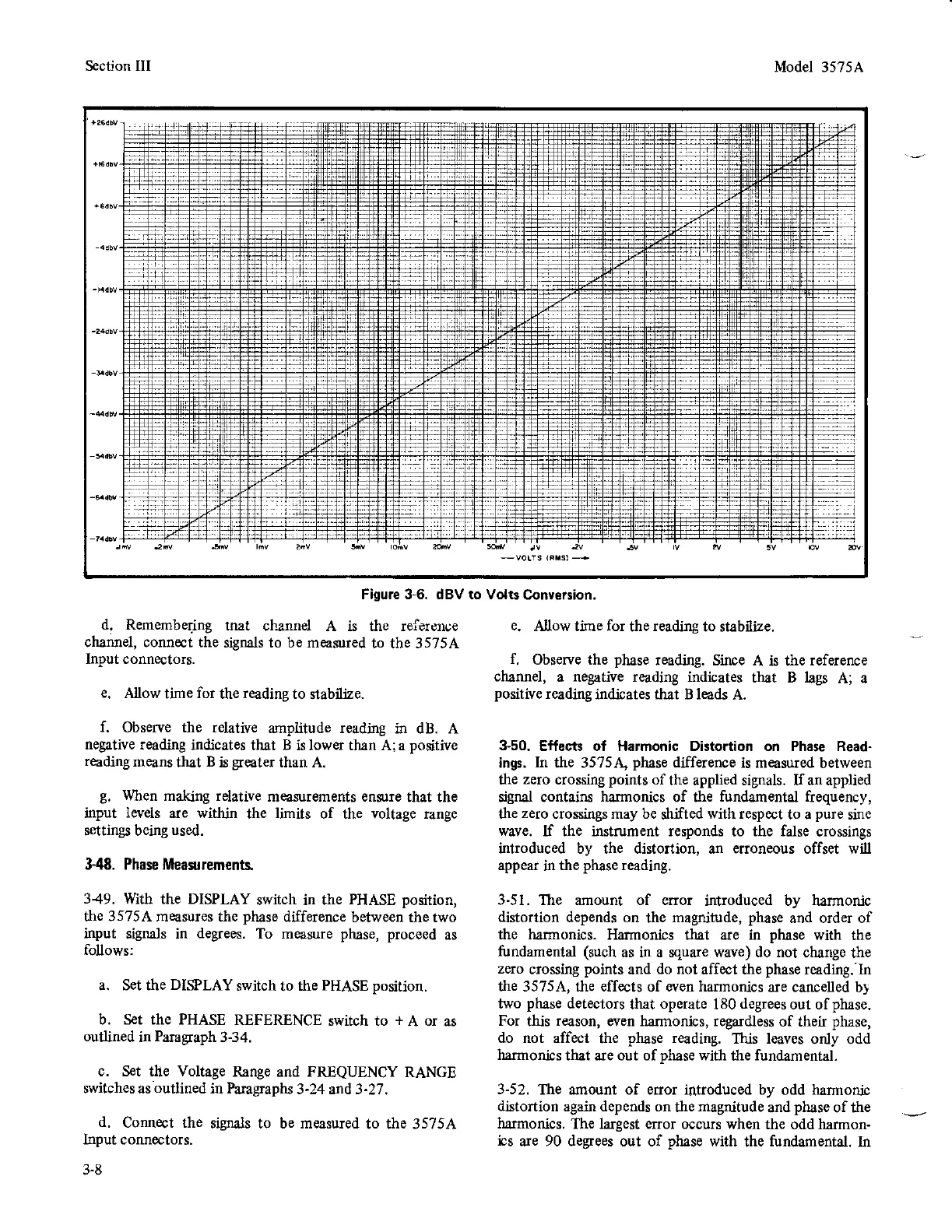
Figure 3-6. dBV to Volts
Conve6ion.