Model 35 75A Section III
@
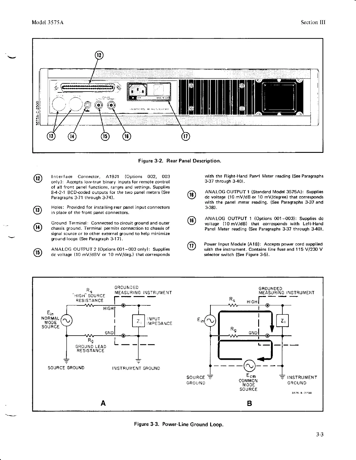
lnterface Connector,
A'19J1
(Oprions
002, 003
only):
Accepts low-true binary
inputs
lor remote control
of all front
panel
functions, ranges and settings. Supplies
8-4-2-1 BCD{oded
outputs for the two
panel
meters
(See
Paragraphs
3'71
through
3'74).
Holes:
Provided for
installingr€r
p6nel
input
connectors
in
place
of the
front
panel
connectors.
Ground Terminal: Connected to circuit
ground
and ouler
chassis
ground.
Terminal
permits
connection to chassis o,
signal source or
to
other external
ground
to
help
minimize
ground
loops
{See
Paragraph
3-17).
ANALOG OUIPUT 2
(Oprions
001-003
only):
Supplies
dc voltage
(10
mV/dBV
or
10 mv/deg.)
that corresponds
Figure 3-2. Rear Panel Oescription,
with the Righr-Hand Pan"l Meter reading
(See
Paragraphs
3-37 through
3-40).
ANALOG OUTPUT 1
(Standard
N4odel 35754): Supplies
dc voltage
(10
mV/dB or 10 mv/deqree) that
corresponds
with the
panel
meter reading.
(See
Paragraphs 3-37 and
338).
ANALOG
OUTPUT 1
(Options
0O1-{03):
Supplies
dc
voltage
(10mV/dB)
that
corresponds
with
Left-Hand
Panel Meter reading
(See
Paragraphs 3-37
through
3-40).
Power lnpur N4odu,e
(A'l8l:
Accepts
power
cord
supplied
\,!ith the instrument. Contains line
fuse
and 1 15 V/230 V
selector switch
(See
Figure 3-5).
R.
HIGH SOURCE
R ES LSTAN
CE
GROUNDED
I\4EASURING
INSTRUIVENT
GROUNDED
MEASURING
lNSTRUIVENT
R9
GROUND LEAD
RESiSTANCE
L
c0rv
Nl0N
IVOOE
SOURCE
B
IN STRU
IV
EN T
GROUND
A
HrGHI
I
Figure
3-3. Power-Line
Ground Loop.
3-3