Section lIl
Model 3575 A
STANDARD
MOD EL
OPTION
001-003
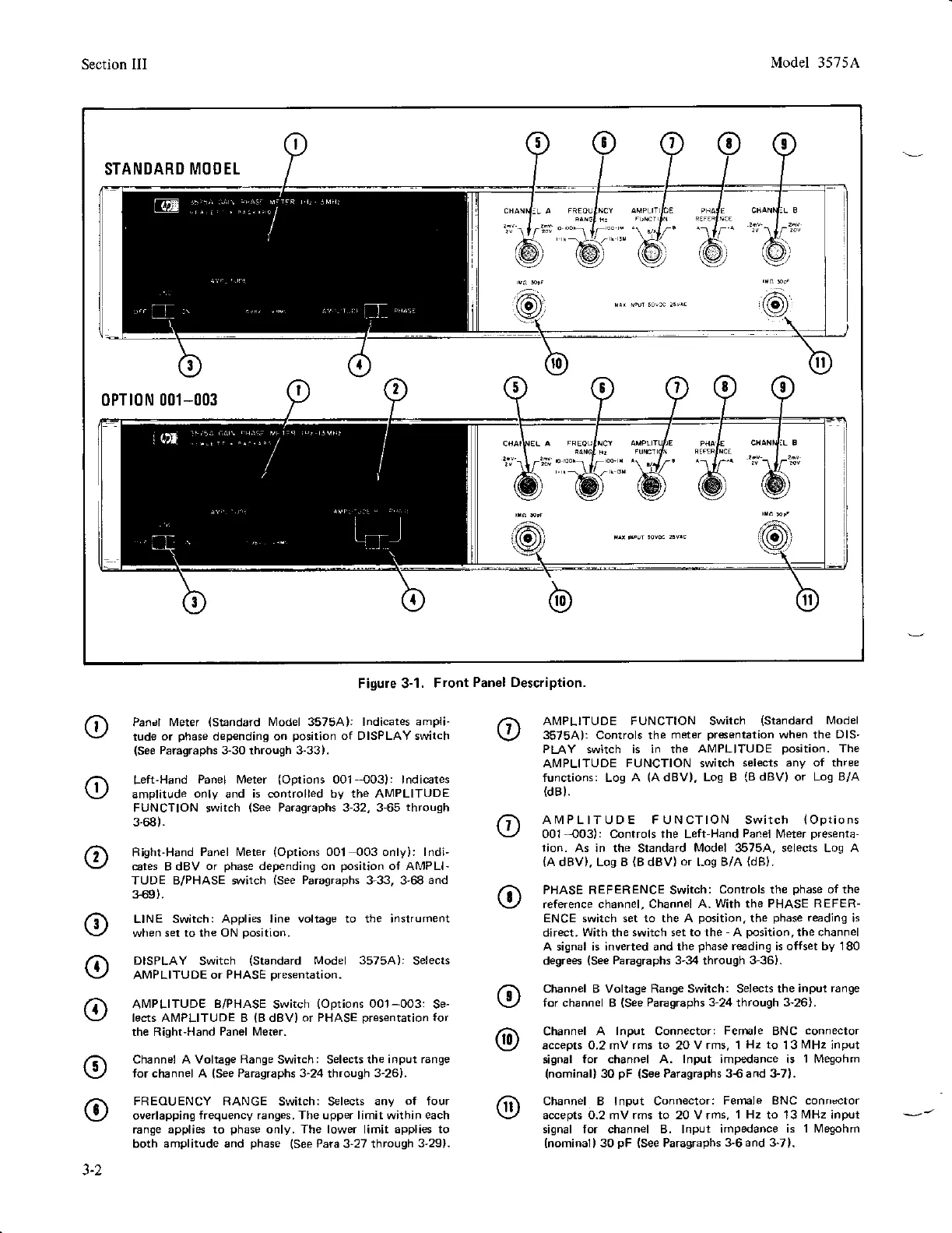
Figure 3-1.
Front
Panel Description.
o
o
o
o
o
Pancl Meter
(Standard
l!4odel
35754):
lndicates ampli-
tude
or
phase
d€pendinq on
position
of DISPLAY switch
(See
Paragraphs 3-30 through 3-33).
Left'Hand
Panel Meter
(Options
00'l-003): lndicates
amptitude
only
and
is
controlled
by the AMPLITUDE
FUNCTION
switch
(See
Paragraphs 3-32, 3-65
through
3-68).
Rlght-Hand
Panel l!4eter
(Options
001 003 only): lndi-
cates B dBV
or
phase
depending on
position
oI AMPLI-
TUDE B/PHASE *vitch
(See
Paragraphs
3-33, 3'68
and
3-69).
LINE Switch:
Applies line voltage to the instrument
when
set to the ON
position.
DISPLAY
Switch
(Standard
Model 3575A):
Selects
AMPLITUDE
or PHASE
presentation.
Al\4PLITUDE
B/PHASE
Switch
(Options
001-003:
Se-
lects ANIPLITUDE B
(B
dBV) or PHASE
presentarion
for
the Righl'Hand
Panel N4eter.
Channel A Voltage
Range
Swirch: Selects the
input range
for channel A
(See
Paragraphs
3-24
through
3-26).
FREOUENCY
FIANGE Switch: Selects
any of four
overlapping
frequency ranges. The upper limit within each
range appliEs
to
phase
only.
The
lower limit
applies to
both amplitude and
phase (See
Para
3"27
through
3'29).
o
@
AIVIPLITUDE FUNCTION Switch
(Standard
Model
35754): Controls the
meter
presentation
when the DIS'
PLAY switch is in the
AMPLITUDE
position.
The
A|PLITUDE
FUNCTION switch
selects any oI three
functions: Log
A
(AdBV),
Log B
{BdBV}
or Log
B/A
(dBl.
AIVIPLITUDE FUNCTION Switch
(Options
001-403): Controls rhe Left-Hand
Panel
[,4eter
presenta-
tion. As in the
Standard
Model 3575A, selects Log A
{A
dBV}. Los B
(B
dBV)
or
Los B/A
(dB).
PHASE REFERENCE Switch:
controls the
phase
o{ the
reference channel, Channel A.
Wirh
the
PHASE REFER-
ENCE
switch
set to the A
position.
the
phase
rarding
is
direct.
With
the
switch set to the
-
A
position.
the channel
A signal is inverted and the
phase
reading is olIset by 180
degrees
(See
Paragraphs 3-34
through
3-36).
Channel B Voltage Range Switch: Selects the
inpul range
for channel B
(See
Paragraphs
3-24
through 3-26).
Channel
A lnput Connector: Fernale BNC
connector
accepts 0.2 mV
rms to
20
V rms, 1
Hz to
13
MHz
input
signal
for channel A. lnput impedance is
'l
l,4egohm
(nominal)
30
pF
(See
Paragraphs 3€ and 3-7).
Channel B lnput Connector:
Femle BNC conncctor
accepts o.2 mvrms to 20 vrms,
I Hz
to 13
MHz
input
signal for channel B. lnput impedance
is 1 l!4egohm
(nominal)
30
pF
(see
Paragraphs
3-6 and 3-71.
3-2