Model 3575A
Scction
III
3575A, the instrument will rcspond to
extraneous
pickup
and
residual noise.
For this
rcason, the displa) ma)' not
stabiiize
until inputs are applied.
3-43. Am
plitude
Measurements.
?44.
Log A and Log B Measurements.
The single channel
anplitude
lunctions
A
or IJ.
permit
direct nleasureinent of
either
input level in dBV. These
readings
can be converted
to ac
volts using the
graph
shown
in Figurc 3-(r. To measure
the
level applied to either input channel.
proceed
as
follows:
a. Set
the DISPLAY switch to the AMPLITUDE
posi-
tion.
b. Set the {\{PLITUDE FUNCTION
switch to
A
or
depending
on rvhich input
is
to be measured.
c. Set the
Voltage
Rangc and
FITEQUEN'CY RANGE
switcher to appropriate settings as
outlined iu Paragraphs
.l-2zl and
-1-17.
1.
2_
3.
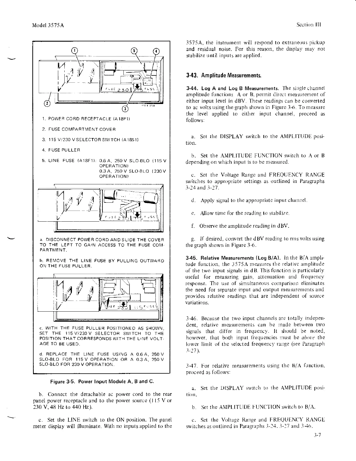
5.
POWE
R
CORD
RECEPTACLE
(A18P1}
FUSE
COMPA
RTMENT
COVE B
]]5
V1230
V SELECTOR
SWITCH
(A18S1)
F
USE
PU
LLE
R
LINE
FUSE
(A18F1),
0.6A,250V
SLOBLO
OPERATION)
0,3 A, 25O V
SLO-BLO
OPE RAIION
)
(11sV
(230
V
a. DISCONNECT POWER
CORD AND
SLIDE
THE
COVER
TO
THE LEFT TO GA1N ACCESS TO
THE
FUSE
COM
PARTMENT,
b, RE[,4OVE
THE LINE FUSE
BY
PULLING
OUTWARD
ON THE FUSE PULLER,
c.
WITH
THE FUSE PULLEB
POSITIONEO AS
SHOWN.
SET
THE 1]5V/230V
SELECTOR SWITCH TO THE
POSITION
THAT CORRESPONDS
WITH THE LIN E VOLT.
AGE TO
BE USE D.
d, REPLACE
THE LINE
FUSE
USING A
0.6A, 25OV
SLO.BLO FOR 115V
OPERATTON OR A 0.3A, 25OV
SLO.BLO FOR 23O V OPERATION
Figure
3-5.
Power lnput l\4odule A. B and C.
b. Connect the
detachable
ac
power
cord to the rear
panel
power receptacle
ard to the
power
source
(l
l5
Vor
230
V, 48 HZ to 44O Hz).
c. Set the LINE switch
to the ON
position.
The
panel
meter display w l illuminate.
With no inputs applied to the
Apply sigral to the appropriatc
input channel
A]low
tirne
tbr
the readinS to stabilirc.
f.
Observe
the alnplitude reading
in
dBV.
g.
II desired, convert the d BV
read,ng to rnrs volts using
the
graph
shown
in Figurc
-l-6.
3-45. Relative
Measurements
(Log
B/A).
In the B/A
ampl-
tude function. the
3575A
measures
the relativc
amplitude
of the two input signals
in
dB.
Tlris
iunction
is
particularly
useful
for
measuring
gain.
attenuatiorl nnl
frecluency
response. The
use
oI siinultaneous
conrparisor)
elinri|ates
the need for separate input and output
measurcmcnts and
provides
relative readings thrt are
independent of
source
variatioIls.
3-46. Because the two
input channels are totally
indcpen-
dent. relativc
nlcasurcrrents
can be madc between two
signals
that dilier
in tiequcrtcy. It should be
noted,
however,
that both
input
iiequencies rnust
be dlr.n
(,
the
lower limit of the selected
frequency rarge
(see
Paragraph
3-.17. For
relative measurements
using thc B/A
function.
proceed
as lirllows:
a. Se1 the
DISPI.AY switcli to
tl're
ANIPLITUDE
posi-
tion.
b. Set
the A,\IPLITUDE
f UNCI
ION
switch
to B,/.\.
c. Set
the Voltage Ilarrge and
FREQUENCY RANCE
switches as outlined in Paragraphs
-l-:.1.
-l-17
anLl
-1J6.
d.
l-'1