Model 1575A
d.
A.llow time
for thc instrumert to
stabil2e
and again
note
the
low level anrplitude reading.
e.
If disconnecting
the high level
signal
ltas
produced
a
significant
change (1 0.5 dB) in the bw
level reading,
a
ground
loop
is
present
and corrective
action
(Paragraph
3-l(r) should
bc
taken.
3-19.
lnpul
Constrainls.
3-10. The E0dB
dynamic range of the 3575A
provides
wide freedonr
lion)
input constraints.
In rnauy cases. it
will
be
possible
to
nral(c all the
necessary mcasurcments without
changing
voltage ranges. It is irnportant.
howcver. to
obscrve the nr&\irnunr
input levcls
(l
V
rrns or
l0
V rms)
indjcated b!
lhe
Voltage
Range settirlg.
Exceedilg tliese
input levels
rvill causc the display to blank.
thc overload
indicator
(AOL
or
861)
to
illullliDatc
alld
car datnage
thc
instrurllcnt
if
the
applied voltage is
greater
than l5 V
rms or
50 V dc.
3-21. DC lsolation.
3-::. Thc
-1575.\
inputs are cquippcd with coupling
capacitors to
pr()\'ide
dc isolation. The maxinunr dc
voltage
that ca be :afeLy applied Lo the inputs is
i
50 Vdc.
Excceding
lhis lirnit can cause
breakdown
of
the
input
capacitors rL'sulting in ddnragc to the ilput
arnplifier
circuitr!.
3-1.1.
fhc
-i575-{
ca
not
be
operated in
a
floating con-
ditioo. All
IupLrt ard Output conrmons are connected
dire.tl) to outer chassis
(iiame) gound
which
connects
to
earth
ground
rluough
the offset
pin
on the
powcr
cord
connector.
3-24. Voltaqe
Banges.
3-15. E3ch input
channel is equipped with a
range
switch
which
pennits
selzution
of
two
overlapping voltage
ranges.
lnput voltage Iirnits rvithin
each
ralge are as
follows:
0.1
rnv rrns (- 74 dBV) to I V mrs
(+
6 dBV)
I
mV rnrs
t
5.1
dBV)
to
l0
V nns
(+
26 dIJV)
3-26. As
long as the applied
sigul
is within the lirnits
ol
both ranges
(2 mV
to I
V), either range settiirg
can
be
used.
Changing
the
voltage
range settilB does
not alfect the
display
resolution- For optimum
accuracy.
however. it
is
recomnrended that the
0.:
nrV to
I
V ran8e by
used at all
tirnes
uniess the applied sigoai is
greater
than I
V rms. The
reason
ior this is that
on
the I
mV
1o l0
V ralgc the input
signal is divided by
the
l0
dB inpul
atteirullor.
Any
noise
tlut
is
gcnerxted
withir the 15754.
however. is not
attenuated
and the sigrul
to noisc ratio is decrcased.
Decreasing
thc sigml
lo noise ratio rnakes
thc instrunrertl
nrorc suseptable to
noise which can affect tl)e accuracy
of
amplitudc
and
phase
rcadings.
It
should bc
noted that the
Phase Accuracy
spocificrtions
(Tabie
l-l) are nret
only'
when the lowest applicable
voltage range scttings arc
Llsed.
Section
III
3-27. Frequency Ranges.
-l-18.
The broadband
frequencl response of
the
-]575A
extcnds from
l tlz to 13 MHz in
four
overlapping ranges.
frequency limjts
within
each range are
as
foUows:
lHztolkHz
I
0
Hz to 100 kHz
100 tlz to I Nltlz
I
kHz to 13 IlHz
3-29.
The
FRIQUENCY RANGE
setting determines
thc
amount
ol filtering that is used throughout
thc iustruntent.
The
filtering, in
turn,
controls the
frequency response and
overall settling time
(See
Tablc
3-l). The
frequcncy ranges
are designed such
that the lower
limit ol each
range
applies
to both
amplitude
and
phase
and
the
upper lirnit
applics
or
y
to
phase.
For
exarrplc, it is
possible
to
use the
1
FL to
I
kHz rangc for
al anplitutlc
mcasurcments witllirl the
liequency range of
I Hz
to l3 NlfL. For most arnplitudc
measuremcnts, however, it is best
to use one of the upper
rarlges k) minimize settlin8
tiine. The main thing to
remember when making
amplitudo n)easurenlents
is
that
the frequency of the input signal(s)
must be above the
lower
limit of
the
selected
frequency range. Vhen mea-
s.rring
phase.
it is necessary
to observe both the upper and
Iower limits of each freque|cy
range.
The
Lrppcr linlits.
which apply to
phase
only. are
dctennined by noise
filters
which
control
the high
frequency
cutoff
characteristics of
the
phase
detector circuits.
For optimurn
phase
accuracy. it
is nocessary to use the
frequency range that
provides
the
greatest
noise immunity
ar./
the required bandpass. This
means
that the 1r)i1'.,J1
range Lhat covers the
frequency of
the input signals must be
used. It
should
be Doted that the
Phase
Accuracy specifications
(Table
1-l) are
rnet only on
the Iowest applicable
frequency range.
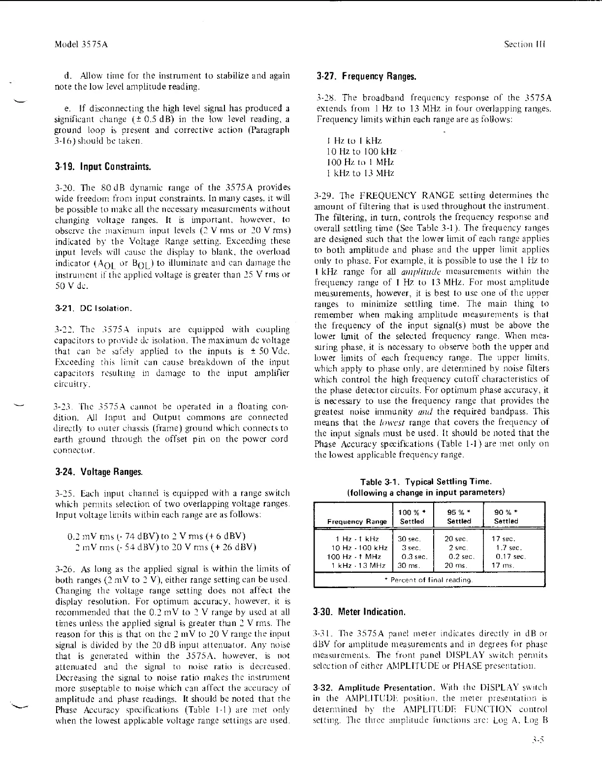
Table 3-1.
Typical Settling
Time.
(Iollowinq
a change
in input
parameters)
100%*
settled
95%*
Settl€d
90%"
Setrled
1 Hz'1 kHz
10 Hz-lO0 kHz
100
Hz 'l MHz
l kHz
.
l3 MHz
30 sec.
3 sec.
0.3 sec.
30 ms
20 sec.
2
sec
0.2 sec.
20 ms
17 sec.
0.1 7 sec.
17 ms.
-
Percent of finrl reading.
3-30.
Meter lndication.
.l-31.
nre
-1575A
panel
nleter indicates direotly in dB
or
dBV for
anlplitude
nreasurenrents
and
in
degrees
for phase
rleasurenler)ls. The
iront
panei
DISPLAY
stvitch
penlits
sclcctiorl of cithcr
ANIPLITUt)E
or PHASE
prcscltatiorr.
3-32. Amplitude Presentation.
With
thc DISI'LAY sritch
ir,
tlre L\IPLlltLrl
p,,.ili,,I.
IIrc rr.lcr
l,re,er,rJIr'..
r'
deternrined
hy lhe
ANIPLITtiDI:
FtINCTIO\ control
sctting.
-llle
tlrr.e irnplitude
iilllctio
s :rrc:
Log
A. Log B
Li
 Loading...


