Model
3575A
PEBFORMANCE
CHECKS
Section
V
FREOU EN CY SYNTHESIZER
hp
33208
GAIN-PHASE
METER
hp 3s75A
50n
FEED
-TH
RU
TERIM INATION
hp ro48c
hp 3s75A
re
o
o
o-o-o
,oooo
rn
?
5r
'r1
\\
/\
)a
FEED-T'iRU
,1 )
IER
lvllNATrON
"r/
/
hp to4ac
/ /
\____/
POWER
SPLITTER
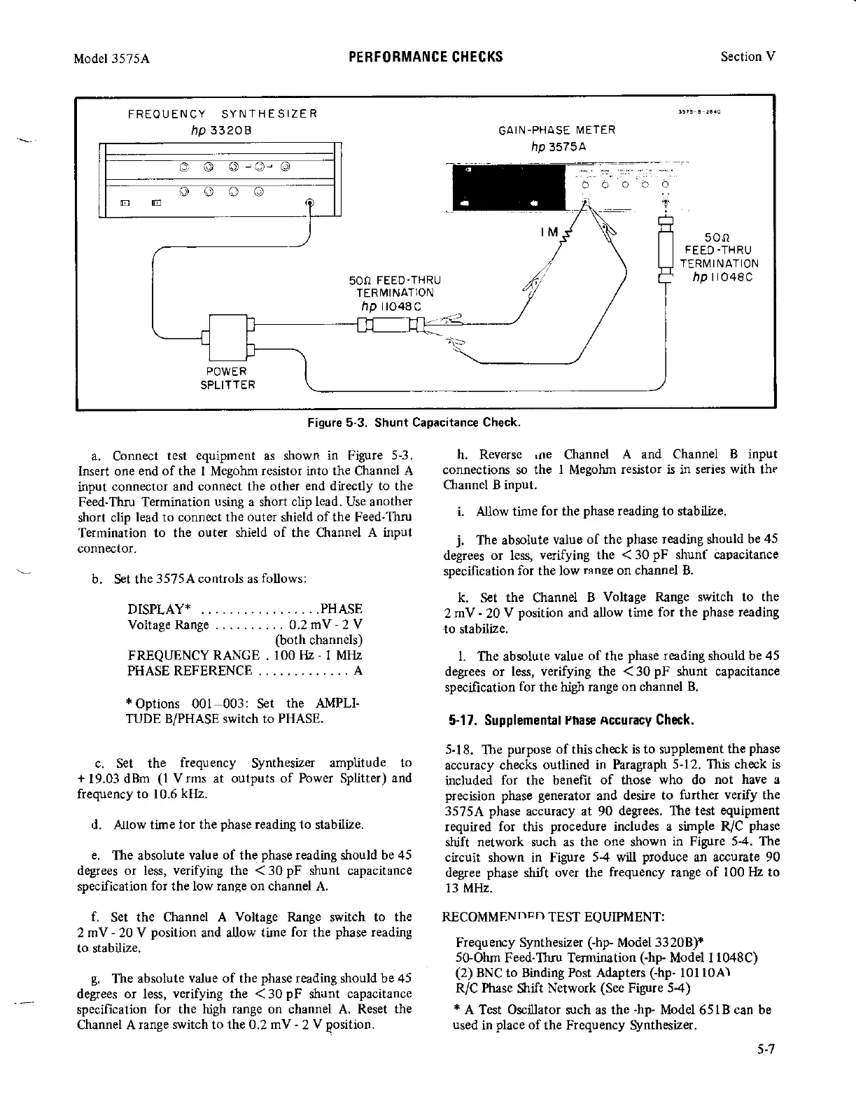
Figure 5-3. Shunt Capacitance Check.
a. Connect
test equipment as shown in Figure
5-3.
h. Reverse loe Channel
A and Channel B inPut
Insert one
end of
the I Megohm
resistor into the Channel A
connections so the I Megohm
resistor is in series
with
the
input connector
and connect the other
end directly to the
Cha[nel B input.
Feed-Thru Termination
using a
short
clip lead. Use another
short c[p
lead to connect th;
outq
shietd
of
the Feed-Thru
i Allow time
for the
phase
reading to stabiLize'
Termination
to the
outer
shield
o[
the Channel
A input
connector.
o"l;"3:,"1x,,:,"..;?ffir"iil.:yd;;.tff,.i:lli##
b. set the
3575A controls as
fbllows:
specification
for the low
mnse
on
channel
B'
DrsplAyx . .
.
.
,
.f!ts.!
,
i"
.Tf
i'i""?,xx';1,f"il:.l'?ff.
xlii"T;::: ,Hrll;
Voltage Range
.
0.2my
-2
V
to stabitize.
ftoth
channels)
FREQUENCY
RANGE
.
100 Hz
-
I MlIz
1.
The absolute
value
of
the
phase
reading should be 45
PHASE REFERENCE . . . . . . . . .
.
.
. . A
degees or less, verifying the <30pF shunt capacitance
specfication
for
the high range
on
channel
B.
*
Options 001 003: Set
the AMPLI-
TUDE B/PHASE switch to
PHASE.
5-17. Supplemental
rnase
nccuracy
Ghck.
5-18.
Ihe
purpose of
this
check is to supplement the
phase
c. Set the
frequency
Synthesizer
amplitude to
accuracy checks
outlined in Paragraph
5-12. This check is
+
19.03 dBm
(l
Vrms at outputs of Power Splitter) and
included
for the benefit
of
those
who do
not have a
frequency to 10.6
kHz.
precis.ion
phase
generator
and
desire to
further verify the
3575A
phase
accumcy
at
90
degrees. The test
equiPment
d. ,AJlow time
lor
the
phase
reading to
stabilize.
required for this
procedure includes a simple R/C
phase
shift network such as the one shown
in Figure 5-4. The
e.
The absolute value
of the
phase
reading
should
be 45
circuit shown in Figure
5-4 will
produce
an accurate 90
degrees or les, verifying the <30pF shunt capacitance
degree
phase
shift over
the
frequency range of 100 tlz to
specification
for
the low
range
on channel A.
13 MHz.
f.
Set the Channel
A Voltage Range switch to the RECOMMENDFD TEST EQUIPMENT:
2 mV
-
20 V
position
and aUow
time for the
phase
reading
to stabilize.
Frequency Synthester
Chp-
Model3320B)*
5GOhm
Feed-Thru Termination
(-hp
Model I 1048C)
g.
The
absolute value of the
phase
reading should be 45
(2)
BNC to Binding Post Adapten
(-hp-
10110A)
defrees or less,
verifying the
i ao
pn
shu,it
capacitance
R/c Phase
Shift
Network
(See
Figure 5-4)
specification
for the high
range
on channel A. Reset
the
*
A
Test
Oscillator
such
as the
-hp-
Model
65lBcan
be
Channel A
range switch
to
the 0.2 mV
-
2
V
position. used
in
place
of
the Frequency Synthesizer.
5-7