Model 3575 A ADJUSTMENT PROCEDURES
Section
V
5.19. ADJUSTMENT PROCEO UHES.
5-10. This
portion
ol
Scction
V contains
complete adjust-
nrent
procedures for the Nlodel 3575A Cain-Phase Meter.
lncluded
are
power
supply adjustrnents
(Paragraph
5-25),
Panel trleter Adjustmcnts
(Paragraph
5-29),
Output
Filter
Zero
Adjustments
(Paragraph
5-33),
Phase Detector
Zero
Adjustnrent
(Paragraph
5--15), Current Source
and
Current
Sink Adjustrnents
(Paragraph
5-37), Amplitude
Offset
Adjustnrent
(Paragraph
5-39), Log
Arnplifier
(amplitude
accuracy) Adjustnlents
(Paragraph
5-.11),
Input Attenuator
Adjustments
(Paragraph
5-43) and
High
Frequency
Phase
Adjustments
(Paragraph
5-45).
5-21. Test Equipment.
5-22.
The test
equiprrcnt recluired for
the adjustmcnts
is
listed in Tablc 5-l and at the beginning
ol
each adjustment
procedurc.
If
the
reconrmended model
is
not
available,
any
instrurnent tllat has specifications
equal
to or better than
the rcquircd specifications can be used.
5-23.
Test
P0int
and
Adiustment Location.
5-2.1.
Test
point
and adjustnent locations are shown in
Figurcs 5-6
(top
view) and 5'7
(panel
metcr). Figures 5-6
and
5-7
are located
on
a single
fold-r-rut
at the
end of
Section
V.
AII
rneasurement
points
are
cither
at the Anaio8
Ouptuts or at designated
pins of
A7P1. Test connector
ATP1 is a male
PC cornector
located at the top
of
the
Phase
Control
Filter
Assembly, A7.
For
convenience
when
maki[g test connectiors to A7Pl, connect a 2X22-Pin
fcnale PC
connector
(hp-
Part No.
1251-1887) to A7P1
and use the
pins
of
the
felrale
connector as test
points.
[f
the appropriate PC cornector is
not
ayailable,
use
the
lxll-Pin
PC extender
(-hp-
5060-5q89)
supplied with the
instrurnent.
All
test rneasurements should be made with
respeot
to circuit
ground
which
is available at ATP1
pin
X
or at any
point
on
the
instrurrent chassis. All adjustrnelts
arc easily
accessible
with
thc top cover
of
the
instrument
rernoved.
It is
not necessary
to
use PC cxtenders or rcmove
any
of
the
PC
assemblics
except
whcn
performing
the
Panel
Nleter AdjustInents, Paragraphs 5,35 through 5-38.
5-25.
+
12
V Reference Adiustmenl.
5-26. This adjustrnent sets the level
ofthe
+
12
Vdc
power
supply
which seryes as a referelce
for
the other
regulated
supplies in the
instrument.
RICONlMENDED TEST EQUIPNIENT:
DC DiBital Voltmeter
1-hp-
Ilodel
-l-150B )
a. Connect
DC
Digiral
Vottmctcr
to
ATPl
pin
6.
b. Adjust Al4R6
for
+
l2
V
13
nlvdc.
5-27.
Power
Supply
Voltage
Checks.
5-18. The
purpose of
these checks is
to verify
that
the
Don-adjustable
power
supply voltages are within design
tolcrances. lf any of the
volta8es
are
out of
tolerance,
refer
to the
Power
Supply Troubleshooting
procedure (Paragraph
s-84).
RECOMMENDED
TEST
EQUIP]VIENT:
DC Digilal Voltrneter
(-hp-
Nlodel
-3,15011)
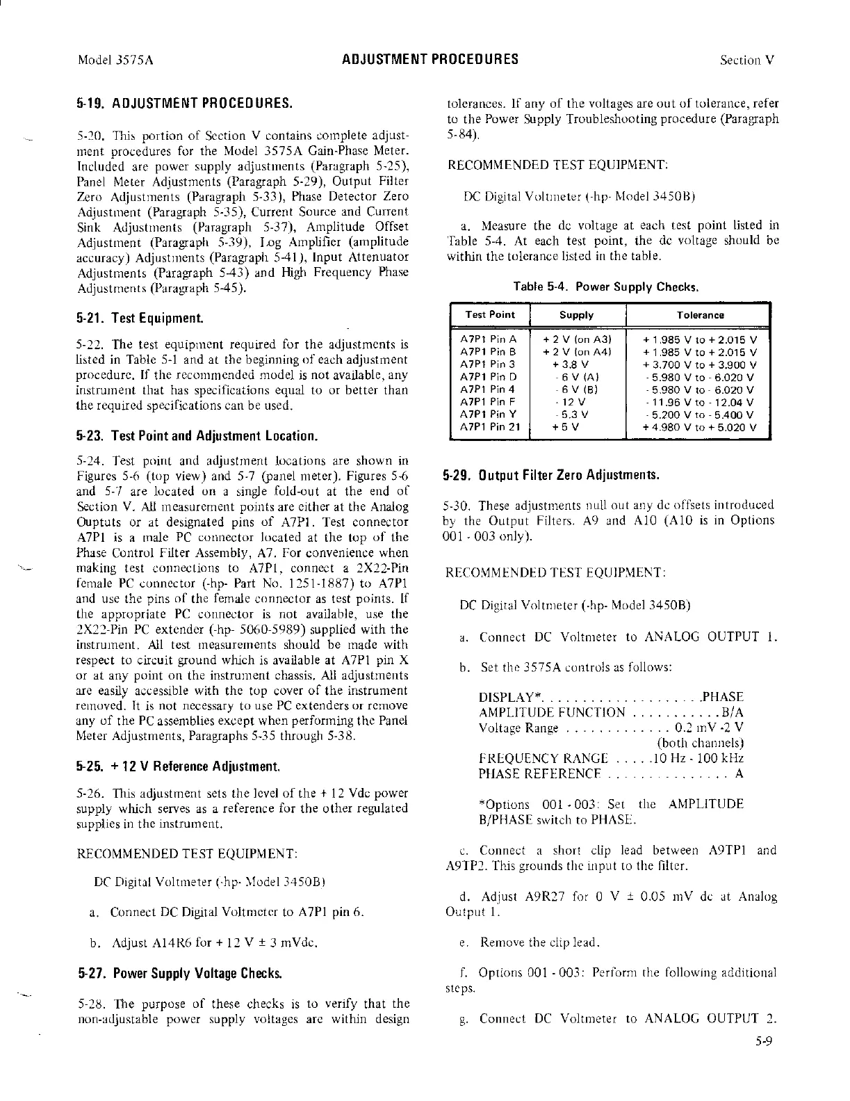
a. Nleasure the
dc voltage at
each
test
point
Iisted in
'Iabte
5-4. At
each
test
point,
the
dc voltage should bc
witlin the tolcrance
listed in the table.
Table
5-4. Power Supply Checks.
Test Point
Supply
ATPl
Pin
B
A7P1
Pin
3
A7P1
Pin
D
A7P1
Pin
4
A7P1
Pin
F
A7P1
Pin Y
A7P1
Pin
21
+2V(on43)
+2V(onA4)
+3.8V
6V(A}
6V(B)
-12V
5.3 V
+5V
+
1.985 V to
+
2.015 V
+
1 .985 V to
+
2.015 V
+
3.700 V to
+
3.900 V
-5.980
V to
-
6.020 V
-
5.980 V to
-
6.020 V
-11-96Vto'1?04V
-5.200
V
to
-
5.400 V
+
4.980 V to
+
5.020 V
5-29. 0utput
Filter Zero Adjustments.
5-30. These
adjustments Dull out
a!'ry dc offsets introduced
by the Output
Filters. A9 and A10
(A10
is in Options
001
-
003
only).
RECO\,1tr,IENDEI] TEST EQUIPIlENT:
DC Di3ital Voltnreter
(-hp-
Model 3450B)
a. Connect
DC Voltnreter to ANALOG OUTPUT 1.
b.
Set the 3575A controls us follows:
DISPLAY*.
, .
.PHASE
AMPLITUDEFUNCTION .,.........8/A
VoltageRange
.....0.2rnV-2V
(botir
channels)
FR|QUENCY RAI'GU . . . .
.10 Hz-
100
kHz
PHASEREFT-RENCE
..,,..,....,.., A
xOptions
001
-003:
Set
tlle ANIPLITUDE
B/PHASE slitch to
I'HASE.
c. Connect a
short clip lead between 49TP1 and
A9TP2. This
grounds
thc illput to the lllter.
d. Adiust
A9R27
lor 0
V
1
0.05
rrtV
dc
at Analog
Output 1.
e. Renrove the ciip lead.
f. Options 001
-
003:
Perform the following additional
stcps.
g.
Connect
DC Voltmeter to ANALOC OUTPUT
l.
5-9