Section I
3575-A-2843
'r.,,
,;i[
;
'{ir
&w{e
;t
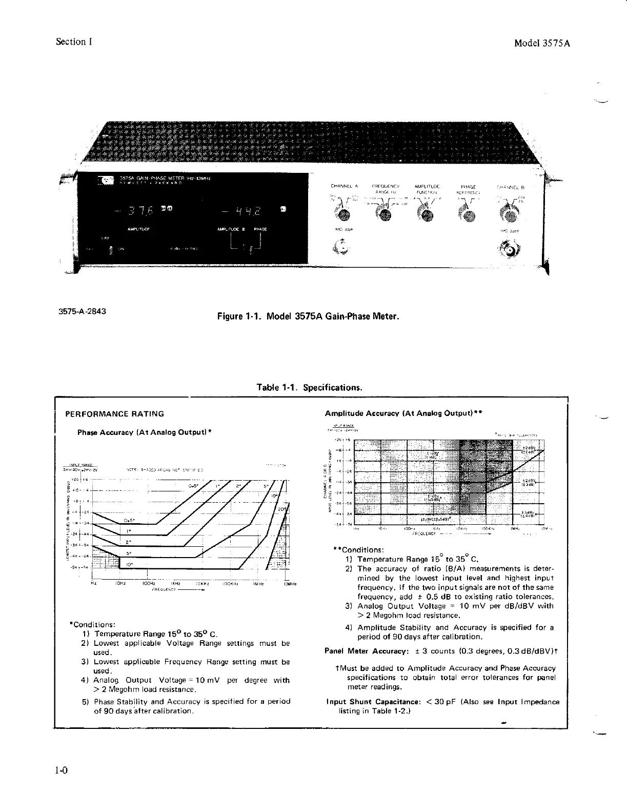
Figure 1-1. Model 35754 Gain.Phase Meter.
Model 3575A
Table 1-1.
Specifications.
PER
FORMANCE
RATING
Phas6 Accuracy
(At
Analog Outpur)*
Amplitude Accuracy
(Al
Analog Output)+'
'Conditions:
'l)
Temperature Range
15o to 35o
C.
2) Lowest applicable Voltage Range settings must be
3) Lowest applicable
Frequency Range
s€tting must be
4) Analog Output Voltage-10mV
per
degree with
>
2
Megohm load resistance.
5)
Phase Stability and
Accuracy is specified
for a
period
o{ 90
days;fter calibrarion.
**Conditionsl
1) T€mperature Range 150 to 35o c.
2) The accuracy of ratio
(B/A)
measurements is deter-
mined by the lowest input level
and highest
input
frequency. lf the
two input
signals are nol of the same
frequency,
add
I
0.5 dB
to existing ratio tolerances.
3) Analog Output
voltage
=
10 mV
per
dB/dBV with
>
2
I\,4egohm
load resistance.
4) Amplitude Stabi,ity and Accuracy
is
specified
for
a
period
of 90 days after calibration.
Panel Meter
Accuracy:
t
3
counts
(0.3
degrees,
O.3dB/dBV)t
tl!4ust be added to Amplitude Accuracy and
Phase
Accuracy
specifications to obtain total
error
tolerances
for
panel
meter readings.
Input
Shunl Capacilance: < 30
pF
(Also
see lnput lmpedance
listing
in Table 1-2.)
t-0