Section I
Model
35 75A
*
Field installable option kits are av6ilable.
**
Options
002
and
003 are identical
except
for
assertion
states of BCD
ourp(s
(se€
Table 1-2).
Option Factory lnsralled*
Dual
Panel Meters
Dual Panel
Meters,
8CD Outputs
and
Remote Control
Kit, Rack
lvlount
Additio'ral
Manual
Ofiion 001
Option
002
Optio'n
002,
003**
Option
908
Option 9'10
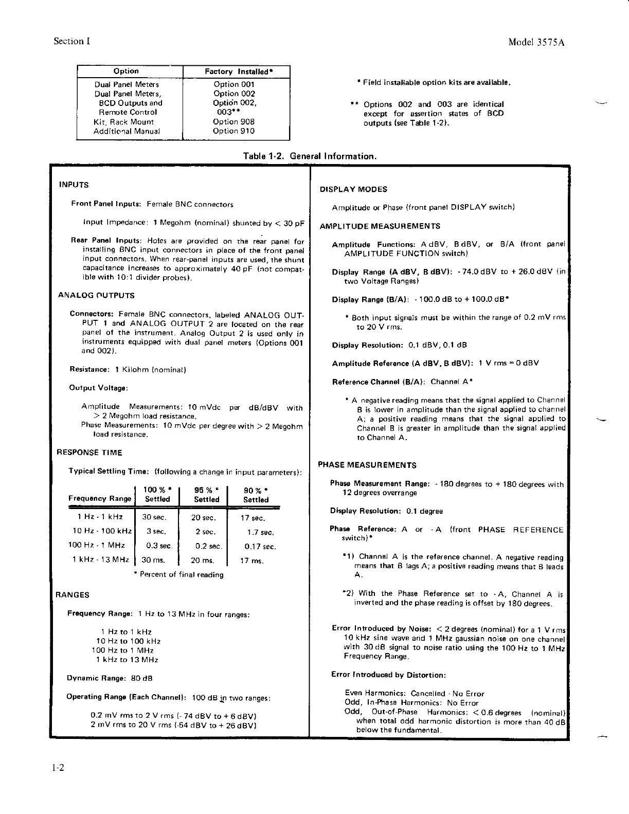
Table'l-2. General lnformation.
INPUTS
Fron!
Panel lnputs:
Female
BNC connectors
lnput
lmpedance:
1 [.4egohm
(nominat)
shunted ty
< 30
pF
Rear Pan€l
lnpuls:
Holes
are
p,ovided
on the rear
panet
for
installing
BNC
input connectors
in
ptace
of rhe front
panel
input connectors.
When
reaFpanel
inputs
are used, the shunt
capacitance
increases to
approximately
40
pF
(not
compat-
ible with
10:1 divider
probes).
ANALOG
OUTPUTS
Connecrors:
Female
BNC connectors,
tabeted
ANALOG OUT-
PUI
1 and ANALOG
OUTPUI
2 are tocared on
the rear
panel
of the instrument.
Analog Output
2 is used only
in
instruments equipped
with
dual
panet
metsrs
loptions
OO1
and 002).
Resistanc€:
1 Kilohm
{nominat)
Output Voltaq6:
Amplitude
l!4easurements:
1O
mVdc
per
dBldBV
with
>
2
Megohm
load
resistance.
Phase
Measurements:
10 mvdc
per
degree
with >
2 M€gohm
load
resistance.
RESPONSE
TIME
Typical
S6ttling
Tim€:
(rollowing
a chanqe
in
DISPLAY
MODES
Amplitude or
Phase
{front
panel
DISPLAY switch)
AMPLITUDE
MEASUREMENTS
Amplitudo F'rnctions:
AdBV, BdBV,
or
B/A
(front
panel
AMPLITUDE
FUNCTION switch)
Display Rango
(AdBV,
BdBV):
-74.0dBV
to
+26.0d8V
(in
two Voltage
Ranges)
Display Rangs
(B/Al: -
100.0dBto+ 100.0d8'
'
Both input
signals must be within
the range of 0.2 mV rms
to
20
V
rms.
Display
Resolution: 0.1 dBV,0.'l dB
Amplitud€ Refer€nce
(A
dBV,BdBV):
1 Vrms=0dBV
R6f6ronce channel
(B/A)i
channel A'
'
A
neqative reading means that the
signal applied to Channel
B is
lower
in
amplitude than the signal applied
to channel
A; a
positive
reading means that
the signal applied to
Channel B is
qreater
in
amplitude than the signal
applied
to
Channel A.
PHASE
MEASUR
EMENTS
Phas€
Measuremsnt
Banger
-
'l80
degrees to
+
'l80
degrees with
'12
degrees overrange
Display
Resolution: 0-l degr€€
Phss€
Referenco:
A or
-A
(front
PHASE
REFERENCE
'1)
Channel A
is
the reference
channe,.
A negative reading
means that
B lags
A;a
positive
reading
means that B
leads
'2)
Wirh rhe Phase
Reference
set to
"A,
Channet
A is
inverted and the
phase
reading is
offset Lly
180 degrees.
Error lntroduced
by Noise:
< 2 degrees
{nominal)
for
a I V
10 kHz
sine
wave and
1 MHz
gaussian
noise
on one channel
with
30dB
signal to noise ratio
using
the 100
Hz to I MHz
Frequency
Range.
Error
Introdrrc€d
by
Distortion:
Even
Harmonics:
Cancelled
-
No Error
Odd, ln+trase
Harmonics:
No Error
input
parameters):
907.*
Seril.d
17 sec.
1.7
sec.
0.17 sec.
17
ms.
100%r
Se lad
95
0/o
'
Seril6d
RANGES
Frequency
Rang€: 1 Hz
to i3lvlHz
jn
four
ranges:
1 Hz'1 kHz
10 Hz
-
100 kH2
100Hz-1MHz
1 kHz
-
13 MHz
l H2 to
10 Hz
to
100 Hz to
1 kHz to
30 sec.
3 sec.
0.3
sec.
30 ms.
20 sec.
2 sec-
0.2 sec.
20 ms.
kHz
00 kH2
MHz
3 MHz
Dynamic
Range:
80 dB
Operating
Range
(Each
Channel):
100 dBin
two ranges:
0.2 mV rms to
2 V rms
(,
74
dBV
to
+
6 dBV)
2 mV rms to
20 V rms
(-54
dBV
ro
+
26dBV)
Odd,
Out-of,Phase
Harmonics:
< 0.6 degrees
(nominat
when total
odd harmonic
distortion
is more
than 40d
below
the fundamental
Percent
of final
reading
1-2