Model
5254C
Section
IV
SECTION
IV
PRINCIPLES
OF OPERATION
4-1.
GENERAL.
4-2,
The Model
5254C
is
a heterodyne frequency con-
verter designed to extend
the
range of frequency meas-
urement
of an
Electronic Counter
to
,
15 GHz through
3
GHz
(150
MHz
through
3000
MHz).
output of the
video amplifier
is monitored
by a meter
circuit which
indicates when
difference frequency
out-
put
amplitude is greater
than the
minimum signal
re-
quired by the counter
input circuit.
Note
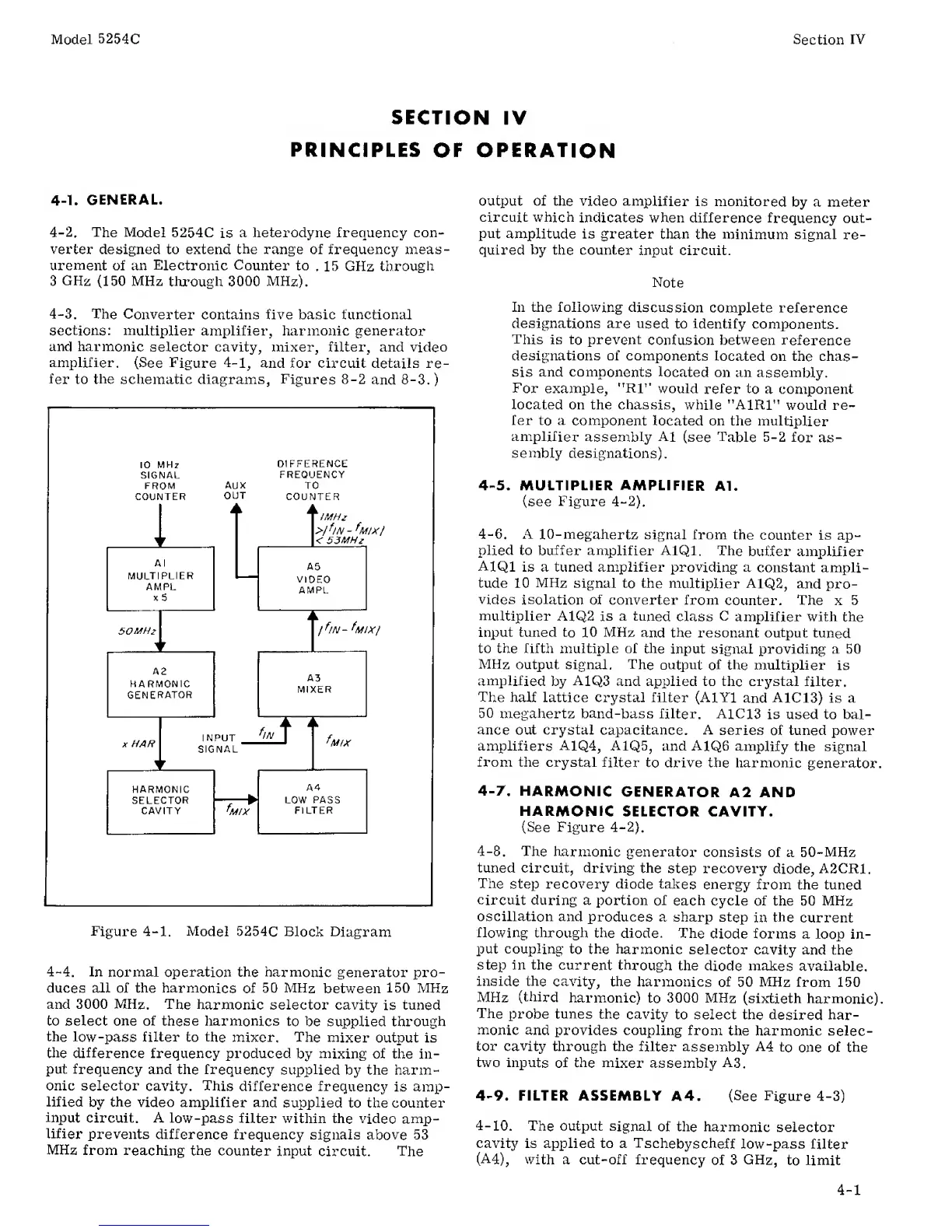
4-3.
The
Converter
contains five basic functional
sections: multiplier
amplifier, harmonic
generator
and
harmonic
selector cavity, mixer, filter, and video
amplifier.
(See Figure
4-1,
and for circuit details
re-
fer
to
the
schematic diagrams, Figures
8-2
and
8-3.
)
10
MHz
SIGNAL
FROM
COUNTER
DIFFERENCE
FREQUENCY
AUX
TO
OUT
COUNTER
Figure
4-1.
Model
5254C
Block Diagram
4-4.
In
normal
operation the
harmonic generator pro-
duces all of the harmonics
of
50
MHz
between
150 MHz
and 3000 MHz.
The
harmonic selector cavity
is
tuned
to select one of these
harmonics
to
be
supplied through
the
low-pass
filter to the
mixer. The
mixer output
is
the difference
frequency
produced
by
mixing of
the in-
put
frequency and
the frequency
supplied by the
harm-
onic
selector
cavity.
This
difference
frequency
is amp-
lified
by
the
video
amplifier and
supplied to
the counter
input
circuit.
A
low-pass filter
within the
video
amp-
lifier
prevents
difference
frequency
signals above 53
MHz
from
reaching
the
counter input
circuit.
The
In the following
discussion
complete
reference
designations are
used
to identify
components.
This is
to prevent
confusion between
reference
designations of
components
located on the chas-
sis
and
components located
on an
assembly.
For
example,
"RF*
would
refer to
a component
located on the chassis, while "A1R1”
would re-
fer
to
a
component
located on the
multiplier
amplifier
assembly
A1
(see Table
5-2
for
as-
sembly designations).
4-5.
MULTIPLIER AMPLIFIER
Al.
(see
Figure 4-2).
4-6.
A
10-megahertz
signal from the
counter is ap-
plied
to
buffer
amplifier A1Q1. The
buffer amplifier
A1Q1
is a tuned amplifier
providing
a constant ampli-
tude 10
MHz
signal
to
the
multiplier
A1Q2,
and
pro-
vides isolation
of
converter from
counter.
The
x 5
multiplier
A1Q2
is
a
tuned
class
C
amplifier with
the
input tuned
to
10 MHz
and the resonant output
tuned
to the
fifth multiple
of
the
input signal providing a 50
MHz
output signal. The
output of
the multiplier is
amplified by
A1Q3
and applied to the crystal
filter.
The
half lattice crystal filter
(AlYl
and
A1C13)
is a
50
megahertz band-bass filter. A1C13
is used to bal-
ance out crystal capacitance. A
series of tuned power
amplifiers
A1Q4,
A1Q5, and A1Q6
amplify
the signal
from
the crystal
filter to drive the harmonic
generator.
4-7.
HARMONIC
GENERATOR
A2 AND
HARMONIC
SELECTOR CAVITY.
(See
Figure
4-2).
4-8.
The
harmonic
generator
consists of
a
50-MHz
tuned circuit,
driving the
step recovery
diode,
A2CR1.
The
step recovery diode takes
energy from the tuned
circuit
during a portion
of each
cycle
of
the 50 MHz
oscillation
and
produces a sharp step
in
the
current
flowing
through the diode.
The
diode forms a
loop
in-
put
coupling to the harmonic
selector
cavity and the
step in the
current
through the
diode makes
available,
inside the
cavity, the
harmonics of
50
MHz
from 150
MHz
(third
harmonic)
to
3000
MHz
(sixtieth
harmonic).
The
probe tunes the
cavity to select the
desired har-
monic
and provides
coupling from
the harmonic
selec-
tor cavity through
the
filter assembly A4
to
one
of
the
two
inputs of
the mixer
assembly
A3.
4-9.
FILTER ASSEMBLY A4. (See Figure
4-3)
4-10.
The
output
signal
of the
harmonic selector
cavity is
applied
to a Tschebyscheff
low
-pass filter
(A4),
with
a
cut-off
frequency
of 3
GHz,
to limit
4-1