Model
5254C
Section
V
SECTION V
MAINTENANCE
5-1.
INTRODUCTION.
5-2.
This section
provides
maintenance and
service
information
for the Model 5254C Frequency Converter.
Included
are a periodic maintenance procedure, a
table
of
recommended test equipment, an
in-cabinet
performance check
which may be used to
verify
proper
operation of the frequency converter, troubleshooting
procedure, and
repair
and adjustment
procedure.
5-3.
PERIODIC
MAINTENANCE.
5-4.
No special maintenance
procedures are required
when the converter
is
operated in normal environments.
However, if unit
is
subjected to
operation in extremely
dusty environments, periodically clean all
gears
with
a
lint-free
cloth and apply a coating of light, petroleum
base,
open-gear
grease
to
all
gear teeth.
5-5.
TEST
EQUIPMENT.
5-6.
Recommended
test
equipment for performance
checking,
troubleshooting
and circuit adjustment after
repair
is listed
in
Table
5-1.
Other
test
instruments
may be used if their
specifications
equal or exceed
the required
characteristics.
5-7.
IN-CABINET PERFORMANCE CHECK.
5-8.
The following
performance check
(Table
5-4)
verifies proper
operation of
all circuits in the
Model
5254C
and may be
used:
a.
as
part of an incoming inspection
check of instru-
ment specifications;
b. periodically,
for
instruments used
in
systems
where maximum reliability is
of
utmost
importance;
c. as part of a
troubleshooting
procedure to
locate
malfunctioning circuits,
and
d. after any
repairs or
adjustments,
before return-
ing instrument to
regular
service.
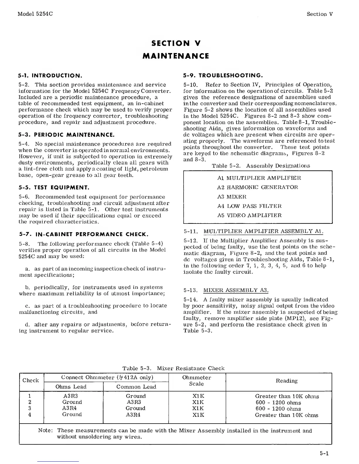
5-9.
TROUBLESHOOTING.
5-10. Refer
to
Section
IV, Principles of Operation,
for information on
the
operation
of
circuits. Table
5-2
gives
the reference designations
of assemblies used
in the converter and their corresponding
nomenclatures.
Figure
5-2
shows
the location of all assemblies used
in the
Model
5254C.
Figures
8-2
and
8-3
show com-
ponent
location on the
assemblies.
Table
8-1,
Trouble-
shooting
Aids,
gives
information
on
waveforms and
dc voltages which are
present when circuits
are
oper-
ating properly.
The waveforms are referenced to test
points
throughout the converter.
These
test points
are keyed to the schematic diagrams,
Figures
8-2
and
8-3.
Table
5-2.
Assembly
Designations
A1
MULTIPLIER
AMPLIFIER
A
2
HARMONIC
GENERATOR
A3 MIXER
A4
LOW
PASS
FILTER
A5
VIDEO
AMPLIFIER
5-11.
MULTIPLIER AMPLIFIER
ASSEMBLY Al.
5-12.
If
the
Multiplier
Amplifier Assembly is sus-
pected of being
faulty, use the test
points
on
the
sche-
matic diagram,
Figure
8-2,
and
the
test points and
dc
voltages given in
Troubleshooting Aids,
Table
8-1,
in the
following order
7, 1, 2, 3, 4, 5,
and 6 to
help
isolate the faulty circuit.
5-13.
MIXER ASSEMBLY
A3,
5-14.
A
faulty mixer assembly
is
usually indicated
by
poor sensitivity, noisy signal
output
from
the video
amplifier. If
the
mixer
assembly is
suspected of being
faulty, remove amplifier
side
plate
(MP12),
see
Fig-
ure 5-2, and perform the resistance
check
given
in
Table
5-3.
Table
5-3.
Mixer
Resistance
Check
—
Check
Connect Ohmmeter
(fy
41
2A
only) Ohmmeter
Scale
Reading
Ohms
Lead
Common
Lead
i
A3R3
Ground
XI
K
Greater
than 10K
ohms
2
Ground
A3R3
X1K
600
-
1200
ohms
3 A3R4
Ground
XI
K
600
-
1200
ohms
4
Ground
A3R4
X1K
Greater
than 10K
ohms
Note: These
measurements
can
be
made
with the
Mixer
Assembly installed in the
instrument and
without
unsoldering any
wires.
5-1