TB 9-6625-2021-35
10
(8) Increase signal generator level output by 1 dB from level recorded in (6) above
and adjust A17A1R22 (fig. 1) ccw until TI display indicates 100 MHz (R).
(9) Verify that sensitivity is at least -32 dBm.
12. Power Supply
NOTE
Do not perform power supply check if all other parameters are
within tolerance.
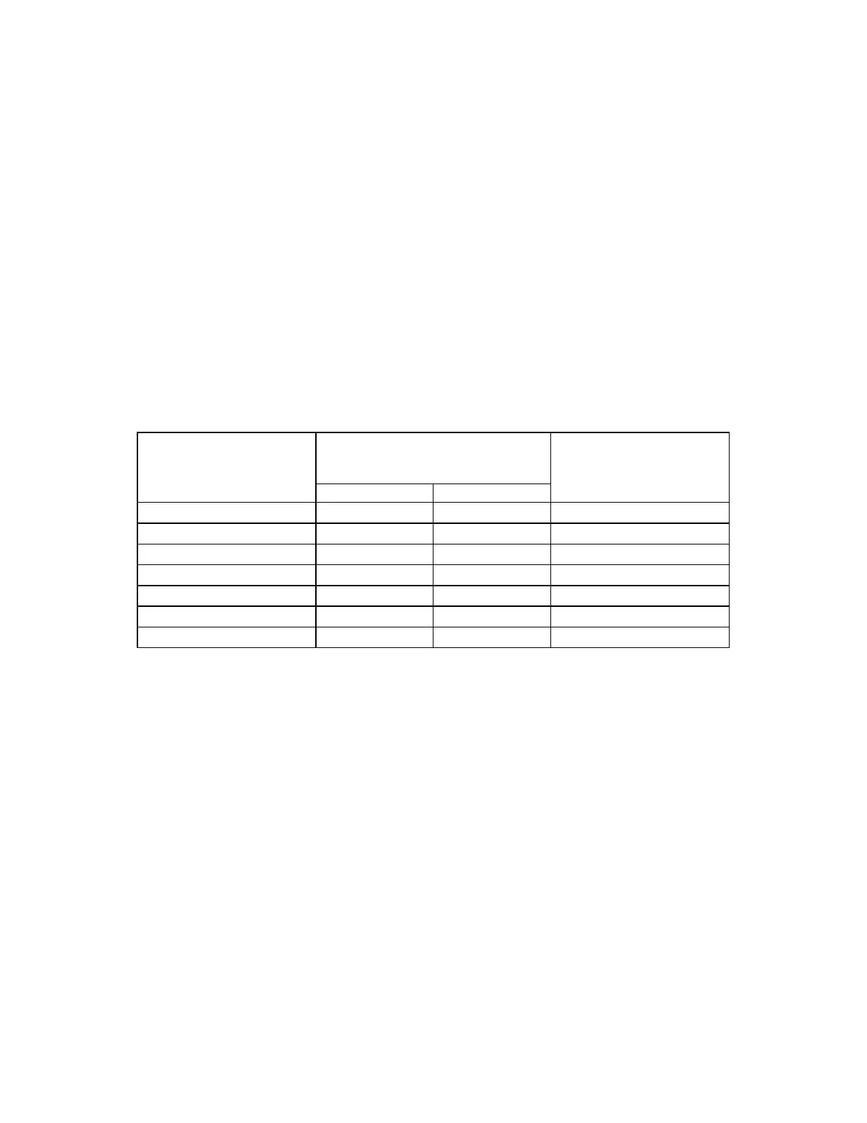
a. Performance Check. Connect multimeter between test points listed in table 4
and chassis ground. If multimeter does not indicate within limits specified, perform
corresponding adjustments in table 4.
Table 4. Power Supply Voltages
Test instrument test
points
Multimeter indications
(V)
Adjustments (R)
(fig. 1) Min Max (fig. 1)
A28TP2 −14.95 −15.05 A28R7
A29TP2 +14.95 +15.05 A29R5
A31TP2 −4.95 −5.05 A31R9
A31TP3 −4.95 −5.05 A31R2
A32TP1 +4.95 +5.05 A32R6
A32TP2 +4.95 +5.05 A32R3
A33TP1
1
+10.95 +11.05 A33R8
1
Option 001 only.
b. Adjustments. No further adjustments can be made.
13. Final Procedure
a. Deenergize and disconnect all equipment.
b. Annotate and affix DA label/form in accordance with TB 750-25.

 Loading...


