2-26
Installing the HP 5400R zl2 Switches
Installation Procedures
Installing the HP 5400R zl2
Switches
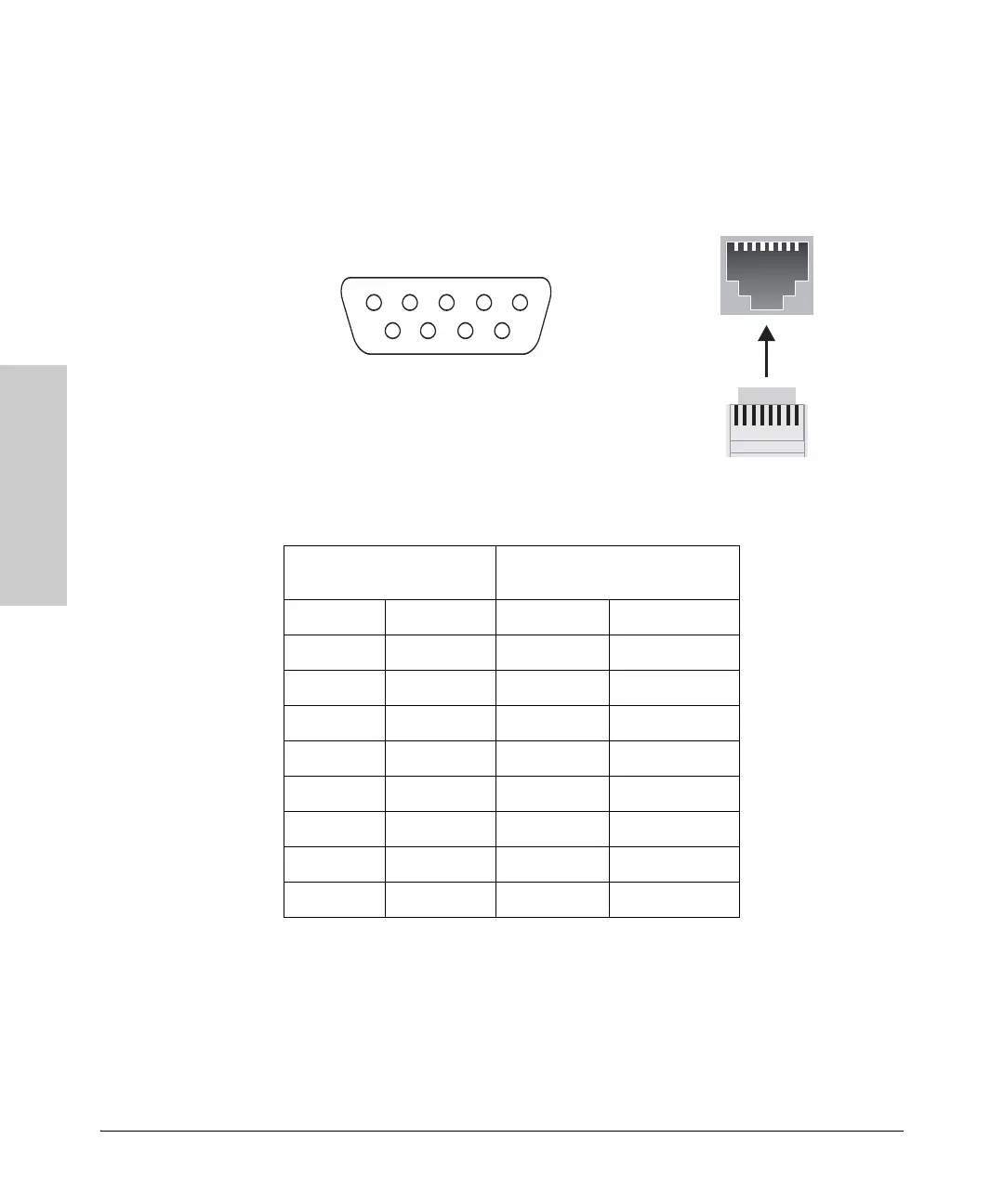
Console Cable Pinouts
The console cable has an RJ-45 plug on one end and a DB-9 female connector
on the other end. Table 2-2 describes the mapping of the RJ-45 to DB-9 pins
module.
Figure 2-7. RJ-45 to DB-9 pinouts
Table 2-2. Mapping of RJ-45 to DB-9
Telnet Console Access
To access the switch through a telnet session, follow these steps:
1. Ensure the switch is configured with an IP address and that the switch is
reachable from the telnet workstation (for example by using a Ping
command to the switch’s IP address)
RJ-45 (Signal reference from
Chassis)
DB-9 (Signal reference from PC)
Reserved 1 8 CTS
Reserved 2 6 DSR
TXD 3 2 RXD
Reserved 4 1 DCD
GND 5 5 GND
RXD 6 3 TXD
Reserved 7 4 DTR
Reserved 8 7 RTS
9 RI

 Loading...