2-17
Installing the HP 5400R zl2 Switches
Installation Procedures
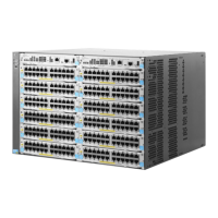
Installing the HP 5400R zl2
Switches
Rack or Cabinet Mounting
The 5400R zl2 switches are designed to be mounted in any EIA-standard 19-
inch telco rack or in an equipment cabinet such as a server cabinet. If you are
installing the switch in an equipment cabinet, read the following “Equipment
Cabinet Note” on
page 2-17.
Equipment
Cabinet
Note
If you are installing the switch in an equipment cabinet, in place of the
12-24 screws supplied with the switch, use the clips and screws that came with
the cabinet. Plan which four holes that you will be using in the cabinet and
install all four clips and partially install the two bottom screws, as described
in step 2 on the previous page, before proceeding to step 3. The number of
holes depends on the switch and the rack kit being used. To reduce the switch
weight and ease while installation, you can remove the power supplies during
the racking process.
WARNING For safe operation, please read the “Installation Precautions” on page
2-6 and page 2-7 before mounting the switch.
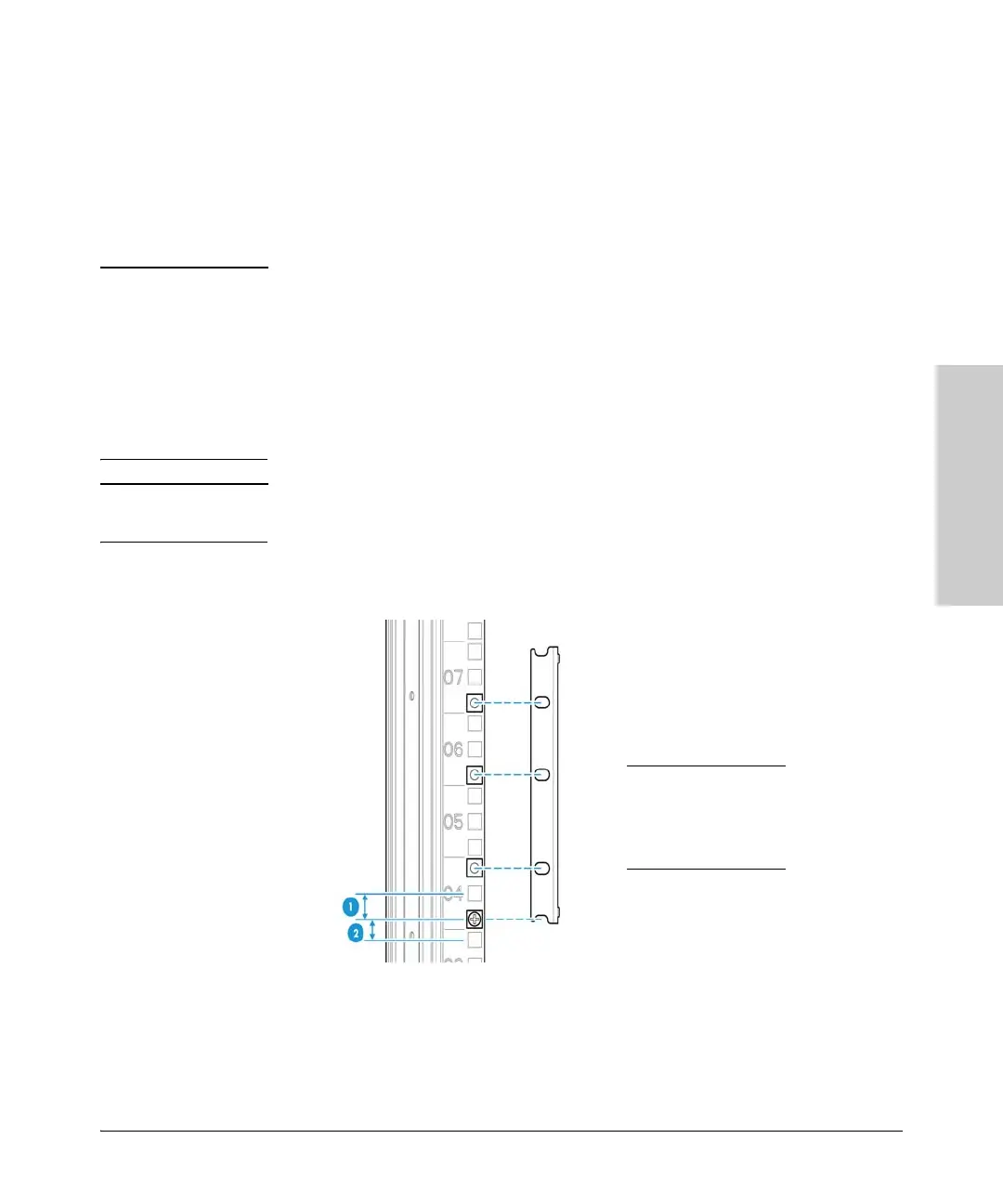
1. Determine position of switch in rack and install a cage
nut in the lower
hole of the lowest rack unit.
1 0.625 inch (1.588
cm)
2 0.50 inch (1.27
cm)

 Loading...