EasyManua.ls Logo

HP 54522A - Page 74

HP 54522A
292 pages
Print Icon
To Next Page IconTo Next Page
To Previous Page IconTo Previous Page
Loading...
Horizontal
Memory
Bar
Memory
Bar
When
the
real-time
mode
is
selected,
the
memory
bar
is
displayed
above
the
graticule
area.
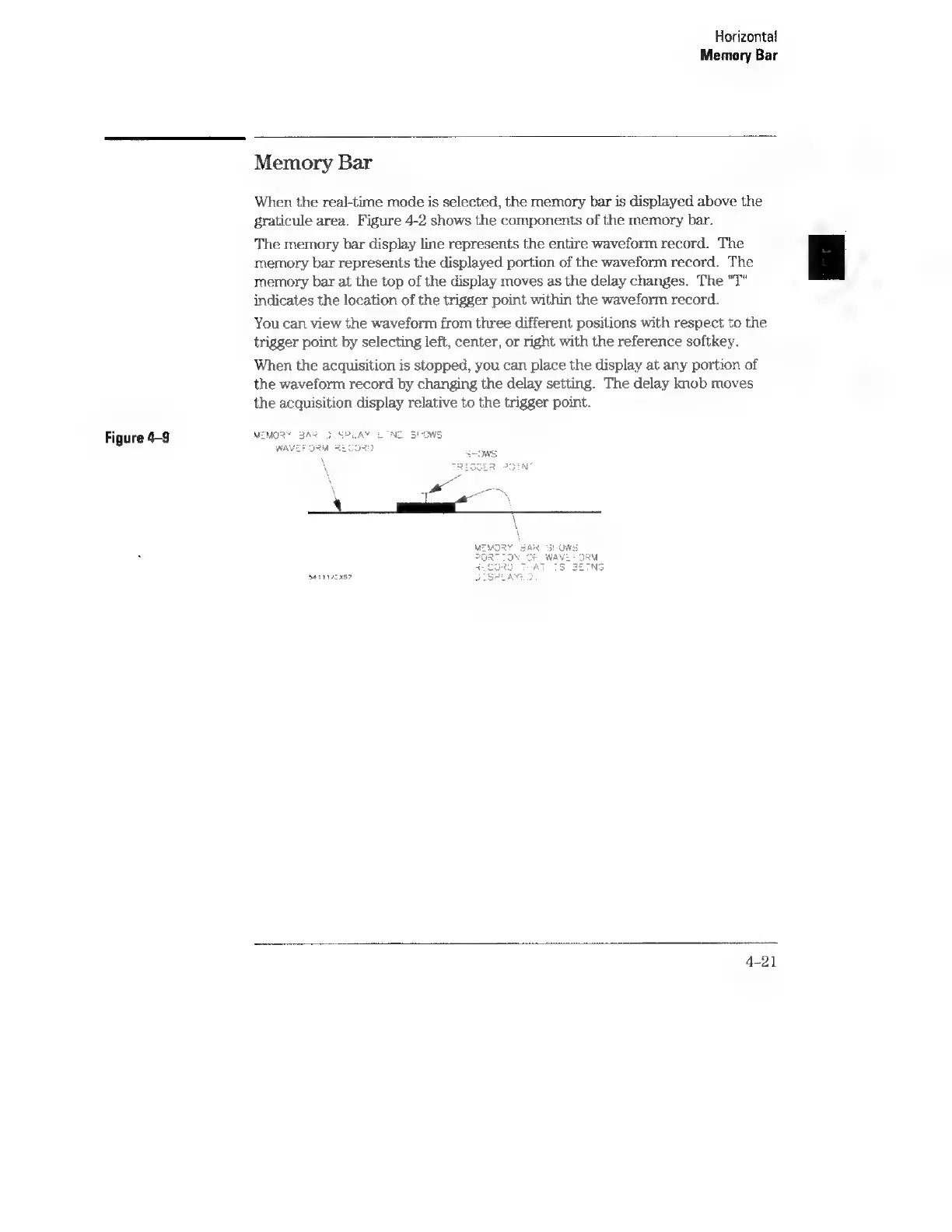
Figure
4-2
shows
the
components
of
the
memory
bar.
The
memory
bar
display
line
represents
the
entire
waveform
record.
The
memory
bar
represents
the
displayed
portion
of
the
waveform
record.
The
memory
bar
at
the
top
of
the
display
moves
as
the
delay
changes.
The
"T"
indicates
the
location
of
the
trigger
point
within
the
waveform
record.
You
can
view
the
waveform
from
three
different
positions
with
respect
to
the
trigger
point
by
selecting
left,
center,
or
right
with
the
reference
softkey.
When
the
acquisition
is
stopped,
you
can
place
the
display
at
any
portion
of
the
waveform
record
by
changing
the
delay
setting.
The
delay
knob
moves
the
acquisition
display
relative
to
the
trigger
point.
Figure
4-9
9411
/x57
4-21