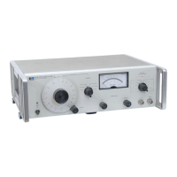
The Hewlett-Packard Model 651B Test Oscillator is a versatile, wide-range capacitance-tuned oscillator designed to generate stable, distortionless sine wave signals across a broad frequency spectrum. This instrument is suitable for various testing and measurement applications, offering precise control over frequency and amplitude.
Function Description:
The Model 651B Test Oscillator generates a sinusoidal signal from 10 Hz to 10 MHz, adjustable across six frequency bands. Its output is continuously monitored by an internal voltmeter, which displays the signal level in RMS volts and dBm. The instrument features an output attenuator for precise signal level control and amplitude coarse and fine adjustments. Two output impedance options are available: 50 ohms and 600 ohms (with an additional 75 ohms for Option 02). The oscillator's core utilizes a modified Wien bridge network for stable, low-distortion signal generation, followed by a power amplifier to boost output power and improve frequency stability under varying loads. A peak detector circuit provides degenerative feedback for amplitude stabilization, and a regulated power supply ensures consistent operation.
Important Technical Specifications:
- Frequency Range: 10 Hz to 10 MHz, divided into 6 bands, with dial calibrations from 1 to 10.
- Dial Accuracy (including warm-up drift and ±10% line voltage variation):
- ±2% from 100 Hz to 1 MHz.
- ±3% from 10 Hz to 100 Hz and 1 MHz to 10 MHz.
- Output:
- Maximum: 3.16 V into 50 Ω or 600 Ω (6.32 V open circuit), equivalent to +23 dBm into 50 Ω.
- Ranges: 0.1 mV to 3.16 V full scale, in 10 steps (1, 3, 10 sequence), with coarse and fine adjustment.
- -70 dBm to +23 dBm (50 Ω output) full scale, 10 dBm per step, coarse and fine adjustable.
- Flatness (Amplitude not readjusted to a reference on the output monitor):
- ±2% from 100 Hz to 1 MHz.
- ±3% from 10 Hz to 1 MHz.
- ±4% from 10 Hz to 10 MHz (applies only at 50 Ω or 75 Ω output; 600 Ω output response above 1 MHz is affected by capacitive loads).
- Output Monitor Accuracy: ±2% of full scale.
- Attenuator:
- Range: 90 dB in 10 dB steps.
- Overall Accuracy: ±0.075 dB (-60 dBm to +20 dBm), ±0.2 dB (-70 dBm to -60 dBm).
- Amplitude Control: 20 dB range (coarse and fine).
- Amplitude Stability: ±2% per month, 20°C - 30°C.
- Distortion:
- Less than 1% from 10 Hz to 2 MHz.
- 2% at 2 MHz to 5 MHz.
- 4% at 5 MHz to 10 MHz.
- Hum and Noise: Less than 0.05% of maximum rated output.
- Temperature Range: 0°C to +50°C.
- Power: 115 V or 230 V ±10%, 30 W, 50 to 1000 Hz.
Usage Features:
- Frequency Dial and Range Switch: The large FREQUENCY dial, combined with the FREQUENCY RANGE switch, allows users to select the desired output frequency. A FREQUENCY VERNIER provides fine adjustment.
- Output Attenuator: The OUTPUT ATTENUATOR switch, in conjunction with AMPLITUDE COARSE and FINE controls, enables precise setting of the output signal level.
- Output Monitor: An integrated voltmeter monitors the signal amplitude in RMS volts and dBm, providing immediate feedback on the output level. A mechanical zero adjust is available for the monitor.
- Output Connectors: The instrument provides output signals via 50 Ω and 600 Ω connectors (or 75 Ω and 600 Ω for Option 02), catering to different impedance requirements.
- Power Selection: A 115/230 V slide switch on the rear panel allows easy conversion between 115 Vac and 230 Vac primary power sources. A pilot lamp indicates when primary power is applied.
- Safety: Equipped with a three-conductor power cable for grounding, ensuring operator safety. A 0.4 ampere slow-blow fuse protects against overloads.
- Options:
- Option 01: dBm scale of the output monitor referenced to 1 milliwatt into 600 ohms, with corresponding changes to the OUTPUT ATTENUATOR dBm markings (-80 to +10 DBM).
- Option 02: Output impedances of 75 ohms and 600 ohms, with the dBm scale referenced to 1 milliwatt into 75 ohms.
- Available Accessories: A range of accessories, including BNC to binding post adapters, line matching transformers, and feed-thru terminations, enhance the instrument's versatility.
Maintenance Features:
- Inspection: The manual emphasizes careful inspection upon receipt for physical damage and electrical performance, with instructions to refer to the warranty if issues are found.
- Power Requirements: Clear instructions are provided for converting between 115 V and 230 V operation, including fuse specifications.
- Installation: The instrument is designed for bench-top use but can be converted to rack-mounted with an optional kit. It is fully transistorized, requiring no special cooling, but should not be operated above 50°C ambient temperature.
- Repackaging for Shipment: Detailed guidelines are provided for safe repackaging, including using original containers or suitable alternatives, proper wrapping, and labeling.
- Instrument Identification: The serial number system is explained, noting that change sheets are provided for instruments with serial numbers differing from the manual's title page, ensuring compatibility and correct documentation.