Do you have a question about the HP 8110A and is the answer not in the manual?
Inspect shipping container for damage and verify instrument integrity before proceeding.
Details AC voltage, frequency range, and maximum power consumption for the HP 8110A.
Information on the three-wire power cable, grounding, and plug identification for different regions.
Specifies required clearances for adequate airflow to prevent overheating and ensure reliability.
Explains overheating detection and automatic shutdown/recovery mechanisms for the instrument.
Information about the internal lithium battery, its replacement, and safety precautions.
Defines suitable operating conditions, including temperature, humidity, and avoidance of hazardous environments.
Highlights features like graphic display and cursor keys for fast, simple operation.
Discusses SCPI commands, rear connectors, and rack height for integration into automated systems.
Emphasizes high pulse integrity, 10 ps timing, and low jitter for consistent, reliable timing.
Explains optional modules like second output, PLL/External Clock, and Deskew that can be added.
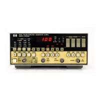
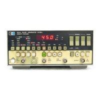
Details the controls and their functions on the instrument's front panel.
Describes the various input and output connectors and their functions on the instrument.
Provides a high-level view of the instrument's main modes like TRG-MODE, TIMING, LEVELS, and OUTPUT.
Overview of the chapter, covering frontpanel controls and parameter screens.
Explains how to access and use the instrument's built-in help system for parameters and commands.
Details the function of softkeys, DATA ENTRY keys, CURSOR/VERNIER, and MODIFY knob.
Guides on viewing and controlling pulse timing parameters on the TIMING screen.
Explains how to view and control pulse level parameters on the LEVELS screen.
Describes the OUTPUT screens for viewing and controlling parameters for one or two channels.
Details on using the PATTERN screen to set up pattern data for outputs.
Guides on setting voltage and current limits to protect the device under test.
Explains how to set triggering thresholds and input impedance for EXT INPUT and STROBE OUT.
Instructions for using the MEMCARD screen for storing and recalling instrument settings.
Details on configuring the instrument, including HP-IB address and grouping parameters.
Lists common IEEE 488.2 commands for the HP 8110A.
Provides a summary of SCPI commands supported by the HP 8110A.
Lists known anomalies and their solutions for firmware revision 02.02.00.
Explains the instrument's status reporting system, including status groups and registers.
Details the bits within the status byte and their meanings for status reporting.
Describes the bits within the Standard Event Status Group.
Details the bits within the Operation Status Group.
Explains the Questionable Status Group bits and their relation to warnings.
Guides on programming the instrument's various trigger modes using SCPI commands.
Overview of the testing chapter and instructions for performing tests.
Explains conventions like softkey labels and display indicators used in the test procedures.
Describes how to interpret and use the tables for recording test results.
Lists essential test equipment and accessories required for performing instrument tests.
Provides initial steps and examples for setting up the instrument for testing.
Illustrates common screen displays encountered during testing procedures.
Explains how to find and record instrument serial numbers for test reports.
Step-by-step guide for the initial configuration of the HP 8110A before performing tests.
Details environmental, safety, power, dimensions, weight, warranty, and conformity specifications.
Covers mainframe timing, configuration, channel addition, output modes, trigger modes, and external input specifications.
| Output Impedance | 50 Ω |
|---|---|
| Duty Cycle | 0.1% to 99.9% |
| Operating Modes | Continuous |
| Trigger Input | TTL compatible |
| Modulation | AM, FM |