1.
Press
4
STIMULUS MENU
5
NNNNNNNNNNNNNN
MORE
NNNNNNNNNNNNNNNNNNNNNNNNNNNNNNNNNNNNNN
TRIGGER MODE
NNNNNNNNNNNNNNNNNNNNNNNNNNNNNNNNNNNNNNNNN
TRIGGER DELAY
.
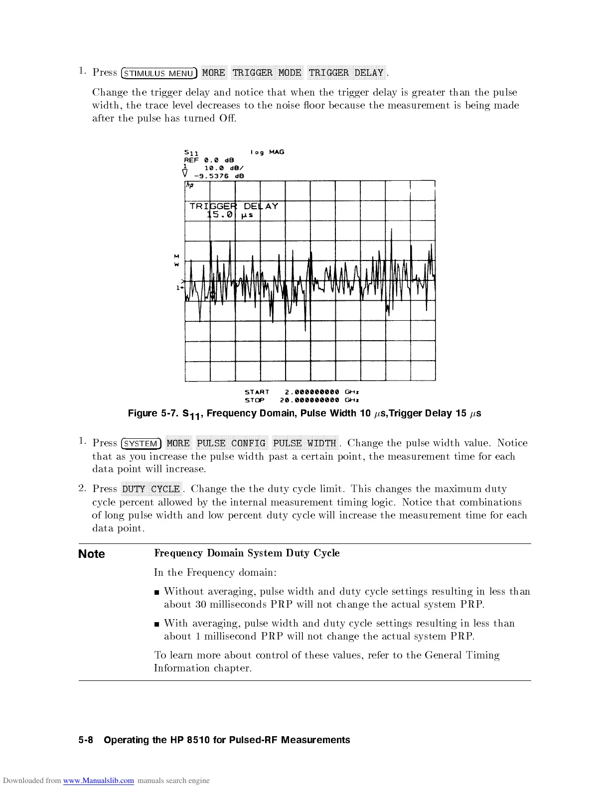
Change the trigger delay and notice that when the trigger delay is greater than the pulse
width, the trace level decreases to the noise o or b ecause the measurement is being made
after the pulse has turned O.
Figure 5-7.
S
11
, Frequency
Domain,
Pulse
Width
10
s,Trigger
Dela
y
15
s
1.
Press
4
SYSTEM
5
N
N
N
N
N
N
N
N
N
N
N
N
N
N
MORE
N
N
N
N
N
N
N
N
N
N
N
N
N
NN
NN
N
N
N
N
N
N
N
N
N
N
N
N
N
N
N
N
N
N
N
N
N
PULSE CONFIG
N
N
N
N
N
N
N
N
N
N
N
N
N
NN
NN
N
N
N
N
N
N
N
N
N
N
N
N
N
N
N
N
N
N
PULSE WIDTH
. Change
the
pulse
width
v
alue.
Notice
that as
you
increase the
pulse width
past
a
certain
p
oin
t,
the
measuremen
t
time
for
eac
h
data
p
oin
t
will
increase.
2.
Press
N
N
NN
NN
NN
N
N
N
N
N
N
N
N
N
N
N
N
N
N
N
N
N
N
N
NN
NN
N
DUTY CYCLE
. Change the the duty cycle limit. This changes the maximum duty
cycle percent allowed by the internal measurement timing logic. Notice that combinations
of long pulse width and low p ercentduty cycle will increase the measurement time for each
data point.
Note
F
requency
Domain
System
Dut
y
Cycle
In
the
F
requency
domain:
Without a
veraging, pulse
width and dut
y cycle settings resulting in less than
about 30 milliseconds PRP will not c
hange the actual system PRP
.
With a
veraging, pulse width
and duty cycle settings resulting in less than
about 1 millisecond PRP will not change the actual system PRP.
To learn more ab out control of these values, refer to the General Timing
Information
c
hapter.
5-8
Operating
the
HP
8510
for
Pulsed-RF
Measurements
 Loading...


