Measure an Amplifier with High Input Levels
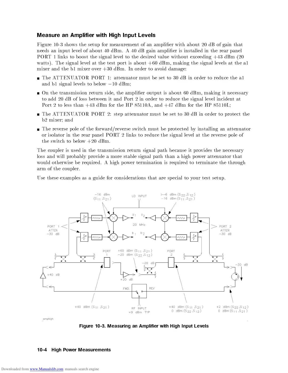
Figure 10-3 shows the setup for measurement of an amplier with about 20 dB of gain that
needs an input level of about 40 dBm. A 40 dB gain amplier is installed in the rear panel
PORT 1 links to b o ost the signal level to the desired value without exceeding +43 dBm (20
watts). The signal level at the test p ort is ab out +60 dBm, making the signal levels at the a1
mixer and the b1 mixer over +30 dBm. In order to avoid damage:
The ATTENUATOR PORT 1: attenuator must b e set to 30 dB in order to reduce the a1
and b1 signal levels to below
0
10 dBm;
On the transmission return side, the amplier output is about 60 dBm, making it necessary
to add 20 dB of loss between it and Port 2 in order to reduce the signal level incidentat
Port 2 to less than +43 dBm for the HP 85110A, and +47 dBm for the HP 85110L;
The ATTENUATOR PORT 2: step attenuator must b e set to 30 dB in order to protect the
b2 mixer; and
The reverse p ole of the forward/reverse switchmust be protected by installing an attenuator
or isolator in the rear panel PORT 2 links to reduce the signal level at the reverse pole of
the
switc
h
to
b
elo
w
+20
dBm.
The
coupler is
used in
the
transmission
return
signal
path
b
ecause
it
pro
vides
the
necessary
loss
and
will
probably
pro
vide
a
more
stable
signal
path
than
a
high
p
o
w
er atten
uator that
w
ould
otherwise
b
e
required.
A
high
p
o
wer
termination is
required
to
terminate
the
through
arm
of
the
coupler.
Use
these
examples
as
a
guide
for
considerations that
are
sp
ecial
to
y
our
test
setup.
Figure
10-3.
Measuring
an
Amplifier
with
High
Input
Lev
els
10-4
High
P
o
w
er
Measurements
 Loading...


