General
Information
Model8555A
Table 1-2. Supplemental Performance Characteristics
SUPPLEMENTAL PERFORMANCE CHARACTERISTICS
~
AMPLITUDE CHARACTERISTICS
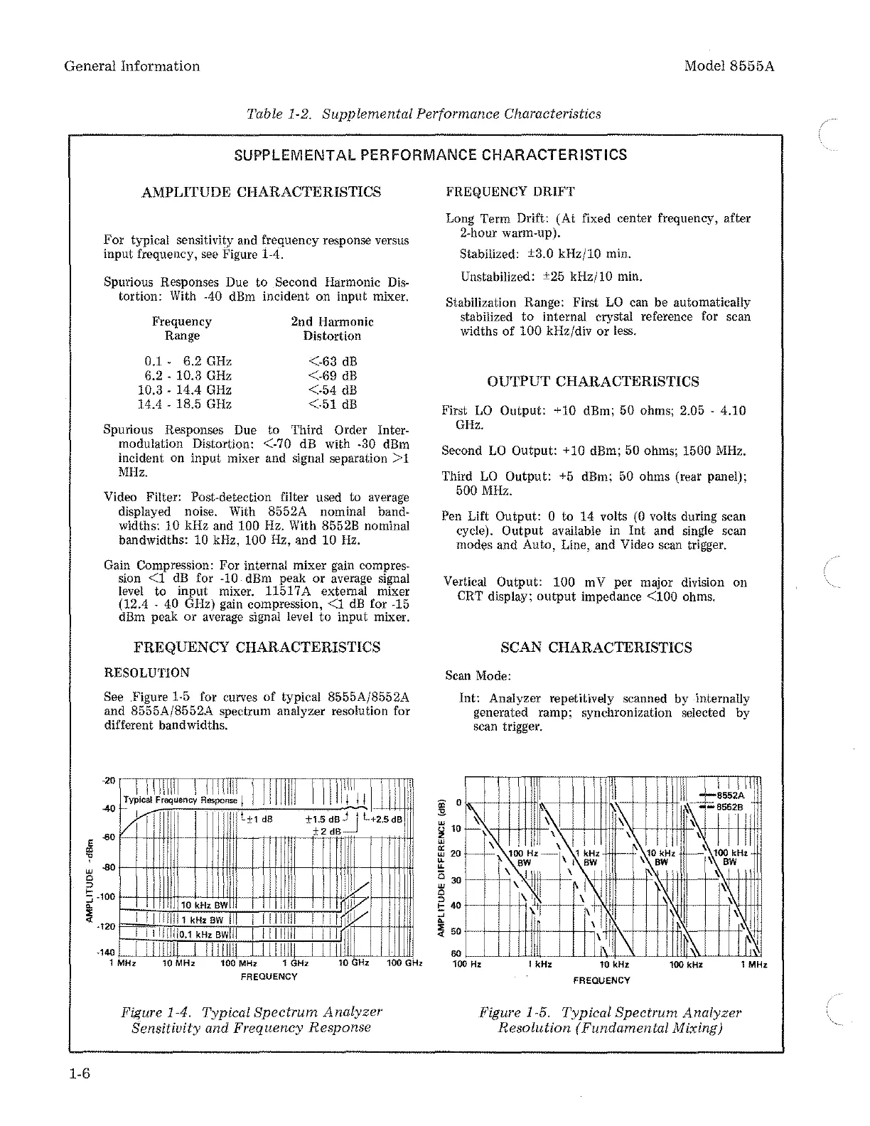
For typical sensitivity and frequency response versus
input frequency, see Figure
1-4.
Spurious Responses Due to Second
Harmonic
Dis-
tortion: With -40 dBm incident on input mixer.
Frequency
Range
0.1 6.2
GHz
6.2 · 10.3
GHz
10.3 · 14.4
GHz
14.4 . 18.5
GHz
2nd
Harmonic
Distortion
<-63
dB
<-69
dB
<-54
dB
<-51
dB
Spurious Responses Due to
Third
Order
Inter-
modulation Distortion: <-70 dB with -30 dBm
incident
on
input
mixer
and
signal separation
>1
MHz.
Video Filter:
Post~detection
filter used to
average
displayed noise.
With
8552A nominal band-
widths: 10 kHz and 100 Hz. With 8552B nominal
bandwidths: 10 kHz, 100 Hz, and 10
Hz.
Gain
Compression:
For
internal mixer
gain
compres-
sion
<1
dB
for
-10
dBm peak
or
average signal
level to input mixer. 11517 A external mixer
(12.4 . 40 GHz) gain compression,
<1
dB
for
-15
dBm
peak or
average
signal
level to input mixer.
FREQUENCY CHARACTERISTICS
RESOLUTION
See Figure 1-5 for curves of typical 8555A/8552A
and 8555A/8552A spectrum analyzer resolution for
different bandwidths.
·20
JL\
1
:IIjll_
IJffillil
1/1//11
1
1
1111
1111
J/1
\1
t!ypical Frequency Response j I I I I f I I
1/
1111
I ·
1111l±1
dB
±l;
~~=-_JL+25ds
1
-40
-60
w -80
0
II
I ll1
~
.
'II
I
'1
i
J.l
\I
ill
.lllif·
, I
t+
j
10kHz
BW
I
II
,
r
~~~
I,
"
~
-100
~
:'i
1-6
I
lll111111kH•BW
Ill
I
1111
Ill
1111nfJJ/
I
l1llllllo.1
kH•
swill
I
11111111
I
Ill
~Ill
. I I IIIII[
IIIIIIIIUII\11111
I
LlJl
·120
·140
1 MHz
10
MHz
100 MHz 1 GHz
10
GHz
FREQUENCY
Figure 1-4. Typical
Spectrum
Analyzer
Sensitivity and Frequency Response
i
100
GHz
FREQUENCY DRIFT
Long Term Drift: (At fixed center frequency, after
2-hour warm-up).
Stabilized: ±3.0 kHz/10 min.
Unstabilized: ±25 kHz/10 min.
Stabilization Range: First
LO
can be automatically
stabilized
to
internal crystal reference for scan
widths of
100
kHz/div or less.
OUTPUT CHARACTERISTICS
First
LO
Output: +10 dBm; 50 ohms; 2.05 · 4.10
GHz.
Second
LO
Output: +10 dBm; 50 ohms; 1500
MHz.
Third
LO
Output:
+5
dBm; 50 ohms (rear panel);
500
MHz.
Pen Lift Output: 0 to 14 volts
(0
volts during scan
cycle).
Output available
in
lnt
and single scan
modes and
Auto,
Line, and Video scan trigger.
Vertical Output: 100 mV per major division on
CRT
display;
output
impedance
<100
ohms.
SCAN CHARACTERISTICS
Scan
Mode:
Int: Analyzer repetitively scanned by internally
generated
ramp;
synchronization selected by
scan trigger.
FREQUENCY
Figure 1-5. Typical Spectrum
Analyzer
Resolution
(Fundamental Mixing)