Model
8555A
General
Information
SECTION
I
GENERAL
INFORMATION
1-1. INTRODUCTION
1-2. This manual
contains
all
information
required
to
install,
operate,
test,
adjust
and
service
the
Hewlett-Packard Model
8555A
Spectrum
Analyzer
RF
Section. This section covers
instrument
identi-
fication, description, options, accessories,
specifica~
tions
and
other
basic
information.
1-3. Figure 1-1 shows
the
Hewlett-Packard Model
8555A
Spectrum
Analyzer
RF
Section with
the
Model 8552B
Spectrum
Analyzer
IF
Section
and
the
Model141
T Display Section.
1-4. The various sections in this manual provide
information as follows:
SECTION II, INSTALLATION, provides in-
formation relative
to
incoming inspection,
power requirements, mounting, packing
and
shipping, etc.
SECTION III, OPERATION, provides infor-
mation relative
to
operating
the
instrument.
SECTION IV, PERFORMANCE TESTS, pro-
vides
information
required
to
ascertain
that
the
instrument
is performing in accordance
with published specifications.
SECTION V, ADJUSTMENTS, provides infor-
mation required
to
properly adjust and align
the
instrument
after
repairs are made.
SECTION VI, REPLACEABLE PARTS, pro-
vides ordering
information
for all replaceable
parts and assemblies.
SECTION VII, MANUAL CHANGES, nor-
mally will
contain
no
relevant
information
in
the
original issue
of
a manual. This section
is
reserved
to
provide back-dated
and
up-dated
information in manual revisions or reprints.
SECTION VIII, SERVICE, includes all in-
formation required
to
service
the
instrument.
1-5.
On
the
title
page
of
this manual, below
the
manual part number, is a "'Microfiche" part
num~
ber. This
number
may
be
used
to
order
4 x 6-inch
microfilm transparencies
of
the
manual. Each
microfiche
contains
UIJ
to
60
photo-duplicates
of
the
manual pages.
The
microfiche package also
includes
the
latest
Manual Changes
supplement
as
well
as
all
pertinent
Service Notes.
1-6. WARNINGS AND CAUTIONS
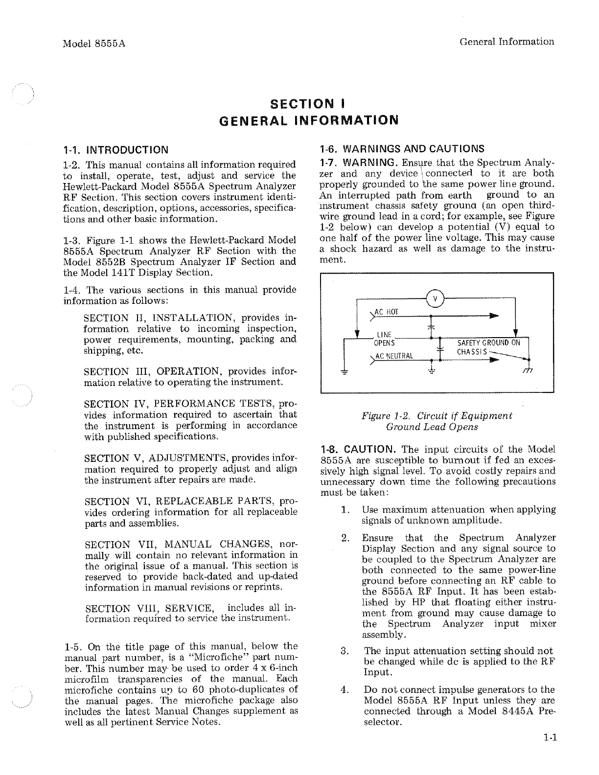
1-7. WARNING. Ensure
that
the
Spectrum
Analy-
zer
and any
device\
connected
to
it
are
both
properly
grounded
to
the
same
power
line ground.
An
interrupted
path
from
earth
ground
to
an
mstrument
chassis safety
ground
(an
open
third-
wire
ground
lead in a cord;
for
example,
see Figure
1-2 below) can develop a
potential
(V) equal
to
one
half
of
the
power line voltage. This
may
cause
a shock hazard as well as damage
to
the
instru-
ment.
~
v
iC
HOT
1
..
LINE
OPENS
)AC
NEUTRAL
,I
-~
Figure 1-2. Circuit
if
.Equipment
Ground Lead
Opens
1-8. CAUTION. The
input
circuits
of
the
Model
8555A
are susceptible
to
burnout
if
fed an exces-
sively high signal level.
To
avoid
costly
repairs
and
unnecessary
down
time
the
following precautions
must
be
taken:
1.
Use maximum
attenuation
when
applying
signals
of
unknown
amplitude.
2. Ensure
that
the
Spectrum
Analyzer
Display
Section
and
any
signal source
to
be
coupled to
the
Spectrum
Analyzer are
both
connected
to
the
same power-line
ground
before
connecting
an
RF
cable
to
the
8555A
RF
Input.
It
has
been
estab-
lished
by
HP
that
floating
either
instru-
ment
from ground
may
cause damage
to
the
Spectrum Analyzer
input
mixer
assembly.
3. The
input
attenuation
setting
should
not
be
changed while
de
is
applied
to
the
RF
Input.
4.
Do
not
connect
impulse generators
to
the
Model
8555A
RF
Input
unless
they
are
connected
through a Model
8445A
Pre-
selector.
1-1