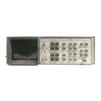
A1
Display Troubleshooting
The Display system consists of four sections:
Input Section A3A8 Analog-Digital Converter and A3A9 Track and Hold
Processor Section A3A4 Memory, A3A5 Data Manipulator, A3A6 Main Control,
and A3A7 Interface
CRT Driver Section A3A1 Trigger, A3A2 Intensity Control, and A3A3 Line
Generator.
CRT Amplifier Section A1A3 High Voltage Regulator and either A1A2 XYZ Driver
Amplifier (Serial Prefixes 3004A and above) or A1A2 Z Axis
Amplifier A1A4 X Deflection Amplifier and A1A5 Y Deflection
Amplifier
Isolation of a malfunction to one of the above sections is done with the use of rear-panel
display outputs and the internal test programs.
If the left INSTR CHECK LED is on, a failure has probably occurred in Digital Storage.
Refer to the A3 Digital Storage Troubleshooting notes for the correct troubleshooting
procedure.
The following paragraphs briefly describe the failure modes and appropriate places to begin
the troubleshooting.
Characters Only
If only the characters on the CRT display are affected, the problem most likely exists on the
A3A4 Memory.
Graticule and Characters Only
If the graticule and characters are incorrect, but the video information appears to be correct,
suspect the System ROMs on A3A6 first. Also the “long POP” test of the RF Section
memory should be performed. Refer to the Digital Storage Troubleshooting notes for more
information.
Al 1

 Loading...