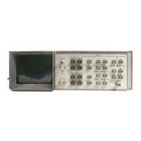
8. Place instrument in position shown in View A of Figure 5 and pull front panel forward to
position shown.
9. Disconnect cable © from A1A10 Motherboard as shown in View A of Figure 5.
Disconnect cable (§) at connector Q)(B) and cable ®G) at connector ®@ on A3A10
Motherboard.
10.
Front panel is now loose from instrument as shown in View B of Figure 5.
11.
To remove A1A1 Keyboard, remove nine screws (T)© used to fasten keyboard to frame.
VIEW A
A1A1 KEYBOARD
VIEW B
Figure 5. Front Panel Removal and Repair, Front Views
6 A1A1

 Loading...