9. Connect the jumper wire from chassis ground to the black wire coming from the A1A11
High-Voltage Multiplier at the wire’s connection to A1A3T1.
10.
Remove all jumper wires. The A1V1 CRT, the A1A3 High-Voltage Regulator, and the
A1A11 High-Voltage Multiplier assemblies should now be discharged.
11.
Remove the bottom cover of the IF-Display section by loosening the screw (7) shown in
Figure 1. Discharge the four large A1A10 Motherboard capacitors by shorting the 2
screws, holding each capacitor to the motherboard, together.
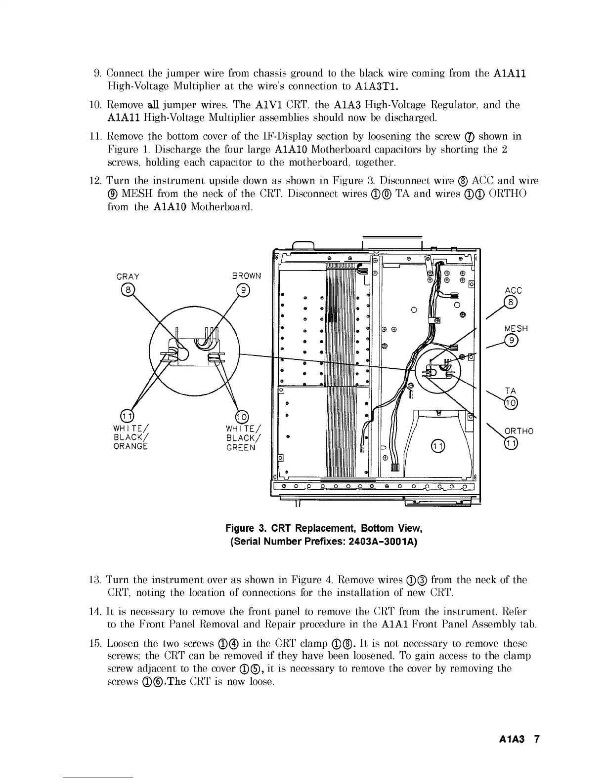
12.
Turn the instrument upside down as shown in Figure 3. Disconnect wire (5) ACC and wire
(9) MESH from the neck of the CRT. Disconnect wires ®(0) TA and wires ©© ORTHO
from the A1A10 Motherboard.
Figure 3. CRT Replacement, Bottom View,
(Serial Number Prefixes: 2403A-3001A)
13.
Turn the instrument over as shown in Figure 4. Remove wires ©© from the neck of the
CRT, noting the location of connections for the installation of new CRT.
14.
It is necessary to remove the front panel to remove the CRT from the instrument. Refer
to the Front Panel Removal and Repair procedure in the A1A1 Front Panel Assembly tab.
15.
Loosen the two screws ©© in the CRT clamp ©(§). It is not necessary to remove these
screws; the CRT can be removed if they have been loosened. To gain access to the clamp
screw adjacent to the cover ©©, it is necessary to remove the cover by removing the
screws ©©.The CRT is now loose.
A1A3 7