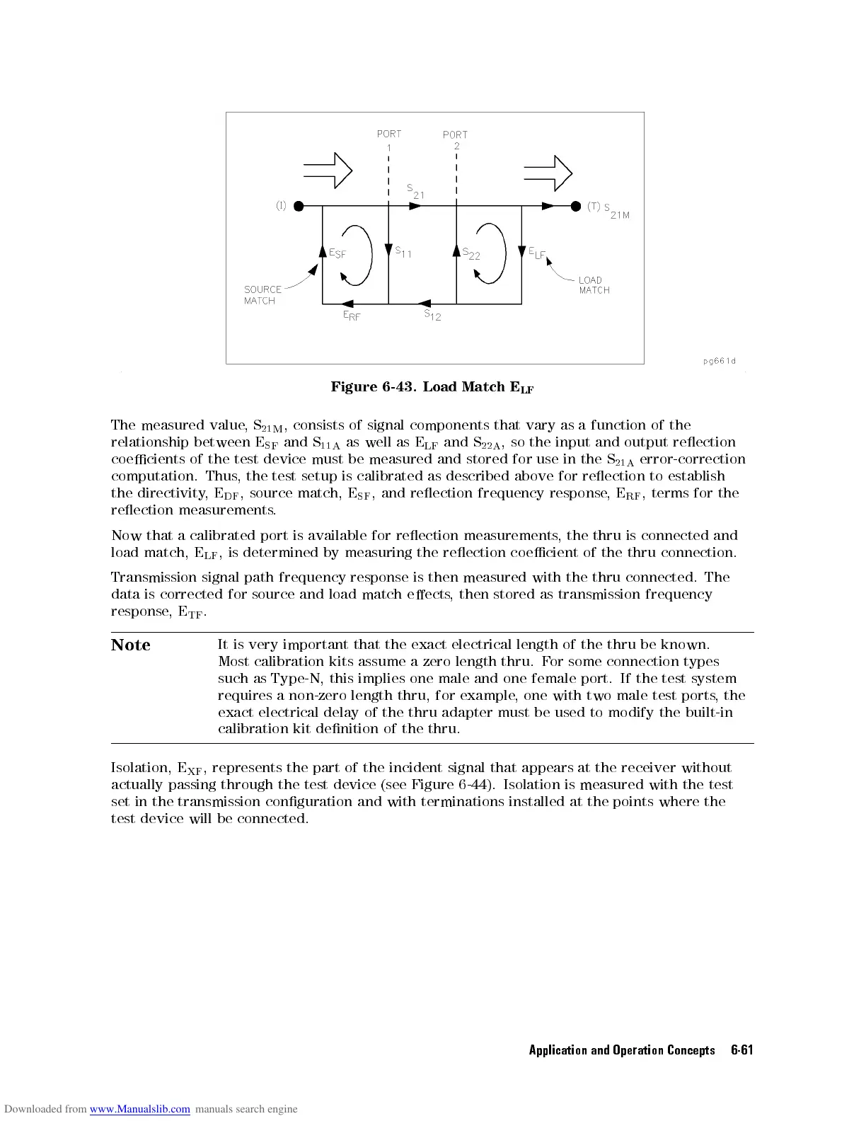
Figure
6-43.
Load
Match
E
LF
The
measured
value
,
S
21M
,
consists
of
signal
components
that
vary
as
a
function
of
the
relationship
between
E
SF
and
S
11A
as
well
as
E
LF
and
S
22A
,
so
the
input
and
output
reection
coecients
of
the
test
device
must
be
measured
and
stored
for
use
in
the S
21A
error-correction
computation.
Thus
,
the
test
setup
is
calibrated as
described above
for
reection
to
establish
the
directivity
,
E
DF
,
source
match,
E
SF
,
and
reection
frequency
response
,
E
RF
,
terms
for
the
reection
measurements
.
Now
that
a
calibrated
port
is
available
for
reection
measurements,
the
thru
is
connected
and
load
match,
E
LF
,
is
determined
by
measuring
the
reection
coecient
of
the
thru connection.
Transmission
signal
path
frequency response
is
then
measured
with
the
thru
connected.
The
data
is
corrected
for source
and
load
match
eects
,
then
stored
as
transmission
frequency
response
,
E
TF
.
Note
It
is
very
important
that
the
exact
electrical
length
of
the
thru
be known.
Most
calibration
kits assume
azero
length thru.
For
some
connection
types
such
as
Type-N,
this
implies one
male and
one female
port.
If
the
test
system
requires
a
non-zero
length
thru, for
example,
one with
two
male
test
ports
,
the
exact
electrical
delay
of
the thru
adapter must
be used
to modify
the
built-in
calibration kit
denition of
the
thru.
Isolation,
E
XF
,
represents the
part
of
the
incident
signal
that
appears
at
the
receiver
without
actually passing through the test device (see
Figure 6-44). Isolation is measured with the test
set in the transmission conguration and with terminations
installed at the points where the
test device will be connected.
Application and Operation Concepts 6-61