How
TRL*/LRM*
Calibration
W
orks
The
TRL*/LRM*
calibration
used
in
the
HP
8753D
relies
on
the characteristic
impedance
of
simple
transmission
lines
rather
than
on
a
set of
discrete impedance
standards.
Since
transmission
lines
are
relatively
easy
to
fabricate
(in
a microstrip
,for
example), the
impedance
of
these
lines
can
be
determined
from
the
physical dimensions
and substrate's
dielectric
constant.
TRL*
Error
Model
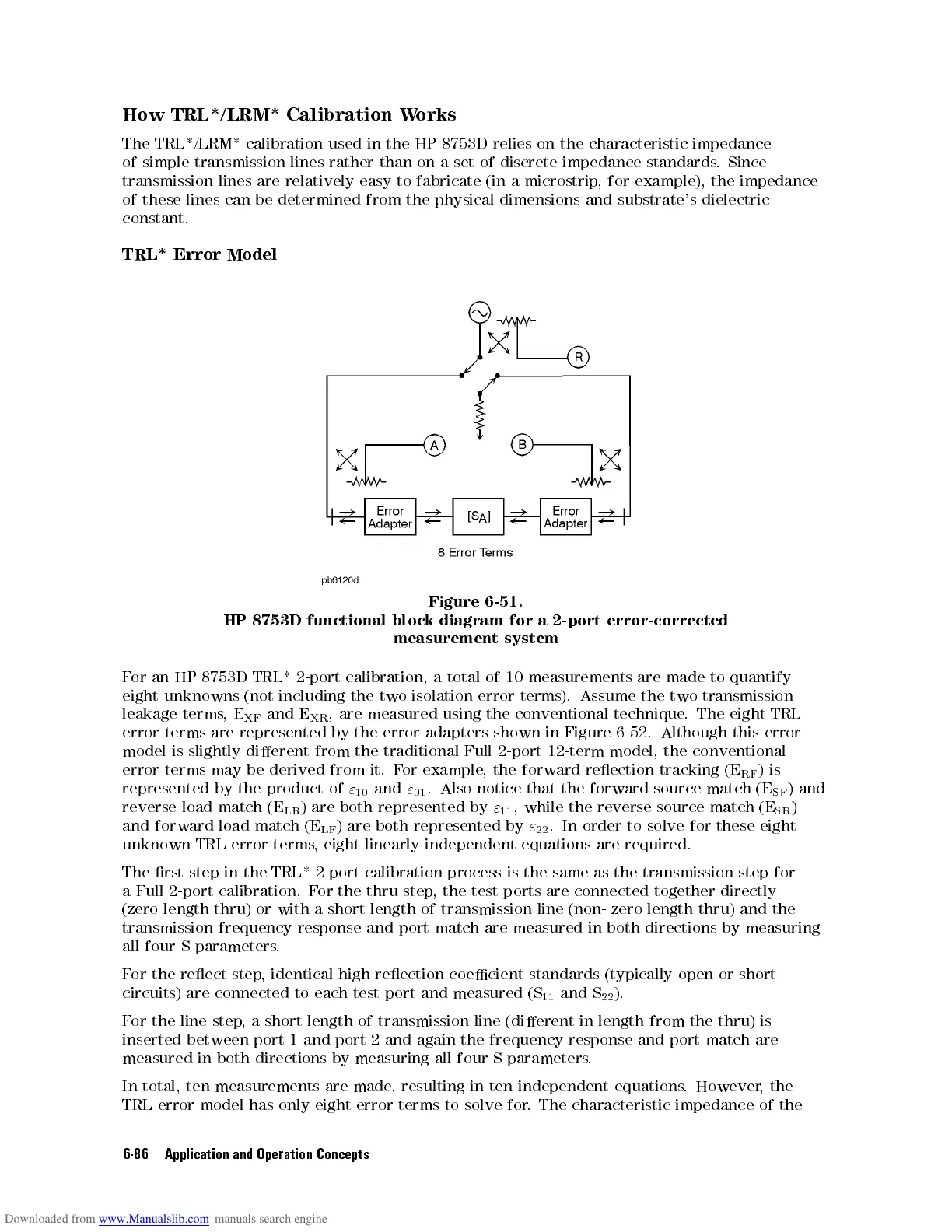
Figure
6-51.
HP
8753D
functional
block
diagram
for
a
2-port
error-corrected
measurement
system
F
or
an
HP
8753D
TRL*
2-port
calibration,
a
total
of
10
measurements
are
made
to quantify
eight
unknowns
(not
including
the
two
isolation
error
terms).
Assume
the
two
transmission
leakage
terms
,
E
XF
and
E
XR
,
are
measured
using
the
conventional technique
.The
eight TRL
error
terms
are
represented
by
the error
adapters shown
in Figure
6-52. Although
this
error
model
is
slightly
dierent
from
the
traditional
Full 2-port
12-term model,
the conventional
error
terms
may
be
derived
from
it.
For
example,
the forward
reection
tracking
(E
RF
)
is
represented
by
the
product
of
"
10
and
"
01
.
Also
notice
that
the
forward
source
match (E
SF
)
and
reverse
load match
(E
LR
)
are both
represented by
"
11
,
while the
reverse source
match (E
SR
)
and
forward load
match (E
LF
)
are both
represented by
"
22
.
In order
to solve
for these
eight
unknown TRL error terms
, eight linearly independent equations are required.
The rst step in the TRL* 2-port calibration process is the same as the
transmission step for
a Full 2-port calibration. F
or the thru step
, the test ports are connected
together directly
(zero length thru) or with a short length of transmission line (non- zero length thru) and the
transmission
frequency response and port match are measured in both directions by measuring
all
four S-parameters
.
For
the reect step
, identical high reection coecient standards (typically open or short
circuits) are connected to each test port and measured (S
11
and S
22
).
For the line step, a short length of transmission line (dierent in length from the thru) is
inserted between port 1 and port 2 and again the frequency response and port match are
measured in both directions by measuring all four S-parameters.
In total, ten measurements are made, resulting in ten independent equations. However, the
TRL error model has only eight error terms to solve for. The characteristic impedance of the
6-86 Application and Operation Concepts
 Loading...


