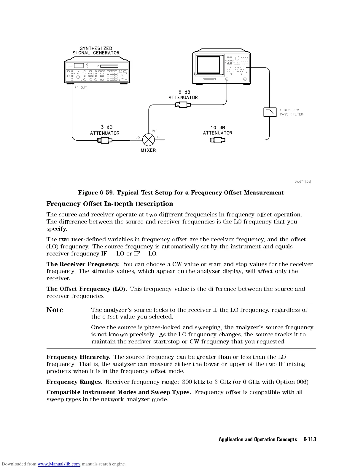
Figure
6-59. Typical
T
est
Setup
for
a
Frequency
Oset
Measurement
Frequency
Oset
In-Depth
Description
The
source
and
receiver
operate
at
two dierent
frequencies
in
frequency
oset
operation.
The
dierence
between
the
source
and
receiver frequencies
is
the
LO
frequency
that
you
specify
.
The two
user-dened
variables
in
frequency
oset
are
the
receiver
frequency
,
and
the
oset
(LO) frequency
.
The
source
frequency
is
automatically
set
by
the
instrument
and
equals
receiver frequency
IF +
LO
or
IF
0
LO
.
The Receiver
Frequency.
Y
ou
can
choose
a
CW
value
or
start
and
stop
values
for
the
receiver
frequency
.
The
stimulus
values
,
which
appear
on
the
analyzer
display
,
will
aect
only the
receiver
.
The
Oset
Frequency
(LO).
This
frequency
value
is
the
dierence
between
the
source
and
receiver
frequencies
.
Note
The
analyzer's source
locks to
the
receiver
6
the
LO
frequency
,
regardless
of
the
oset
value
you
selected.
Once the source is phase-locked and sweeping, the analyzer's source frequency
is not known precisely
. As the LO frequency changes
, the
source tracks it to
maintain the receiver start/stop or CW frequency that you requested.
Frequency Hierarchy
.
The source frequency can be greater than or less than the LO
frequency.Thatis
, the analyzer can measure either the lower or upper of the two IF
mixing
products when it is in the frequency oset mode
.
Frequency Ranges.
Receiver frequency range: 300 kHz to 3 GHz (or 6 GHz with Option 006)
Compatible Instrument Modes and Sweep Types.
Frequency oset is compatible with all
sweep types in the network analyzer mode.
Application and Operation Concepts 6-113