Model
8901B
Service
At this point the LO
is
configured as in Figure 8D-1, and the tuning continues as in the manual tune
mode using the computed frequency in place of a keyboard-entered frequency.
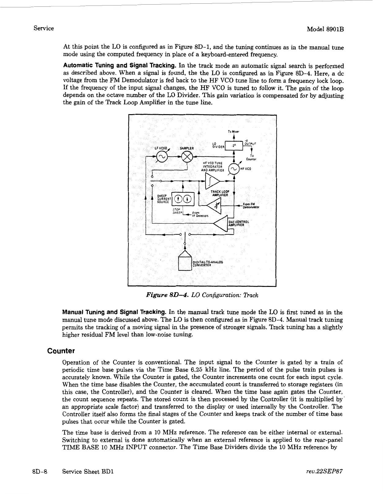
Automatic Tuning and Signal Tracking.
In
the track mode an automatic signal search
is
performed
as described above. When a signal is found, the the
LO
is
configured as in Figure
8D-4.
Here, a dc
voltage from the FM Demodulator is fed back to the HF VCO tune line to form a frequency lock loop.
If
the frequency of the input signal changes, the
HF
VCO is tuned to follow it. The gain of the loop
depends on the octave number of the
LO
Divider. This gain variation
is
compensated for by adjusting
the gain of the Track Loop Amplifier in the tune line.
Manual Tuning and Signal Tracking.
In the manual track tune mode the
LO
is first tuned as in the
manual tune mode discussed above. The LO
is
then configured as in Figure
8D-4.
Manual track tuning
permits the tracking of a moving signal in the presence
of
stronger signals. Track tuning has a slightly
higher residual FM level than low-noise tuning.
Counter
Operation of the Counter
is
conventional. The input signal to the Counter is gated by a train of
periodic time base pulses via the Time Base
6.25
kHz line. The period of the pulse train pulses is
accurately known. While the Counter is gated, the Counter increments one count for each input cycle.
When the time base disables the Counter, the accumulated count is transferred to storage registers (in
this case, the Controller), and the Counter is cleared. When the time base again gates the Counter,
the count sequence repeats. The stored count
is
then processed by the Controller
(it
is
multiplied by'
an appropriate scale factor) and transferred to the display
or
used internally by the Controller. The
Controller itself also forms the final stages of the Counter and keeps track of the number of time base
pulses that occur while the Counter
is
gated.
The time base
is
derived from
a
10 MHz reference. The reference can be either internal
or
external.
Switching to external
is
done automatically when an external reference is applied to the rear-panel
TIME
BASE
10
MHz INPUT connector. The Time Base Dividers divide the
10
MHz
reference by
reu.22SEP87
8D-8
Service Sheet
BD1