Model 8903B Service
SERVICE SHEET BD1-Overall
Block
Diagram
PRINCIPLES
OF
OPERATION
General
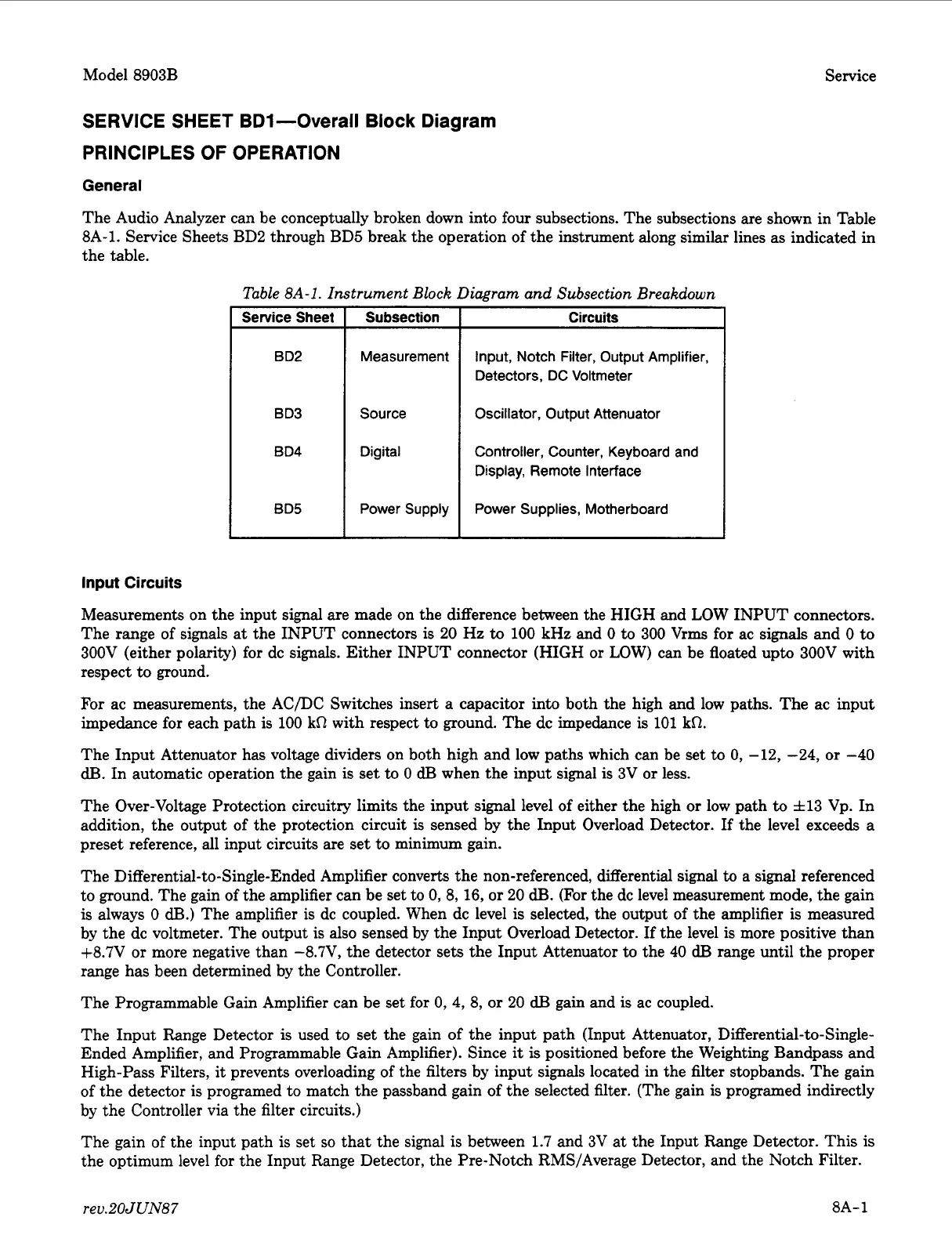
The Audio Analyzer can be conceptually broken down into four subsections. The subsections are shown in Table
8A-1.
Service Sheets BD2 through BD5 break the operation of the instrument along similar lines
as
indicated in
Service Sheet
B
D2
the table.
Input
Circuits
Subsection Circuits
Measurement Input, Notch
Filter,
Output
Amplifier,
Detectors,
DC
Voltmeter
BD4
Oscillator, Output Attenuator
BD3
I
Source
I
Digital
Controller, Counter, Keyboard and
Display, Remote Interface
BD5
I
Power
Supply
I
Power Supplies, Motherboard
I
Measurements on the input signal are made on the difference between the HIGH and LOW INPUT connectors.
The range of signals at the INPUT connectors
is
20
Hz
to
100 kHz and
0
to
300
Vrms for ac
signals
and
0
to
300V (either polarity) for dc signals. Either INPUT connector (HIGH
or
LOW) can be floated upto 300V with
respect to ground.
For ac measurements, the AC/DC Switches insert a capacitor into both the high and low paths. The ac input
impedance for each path is 100
kR
with respect to ground. The dc impedance
is
101 kR.
The Input Attenuator has voltage dividers on both high and low paths which can be set to
0,
-12, -24,
or
-40
dB.
In automatic operation the gain
is
set to
0
dB
when the input signal is 3V
or
less.
The Over-Voltage Protection circuitry limits the input signal level of either the high
or
low path
to
f13
Vp. In
addition, the output of the protection circuit
is
sensed by the Input Overload Detector.
If
the level exceeds a
preset reference, all input circuits are set to minimum gain.
The
Differential-to-Single-Ended
Amplifier converts the non-referenced, differential signal
to
a
signal referenced
to ground. The gain of the amplifier can be set to
0,
8,16,
or
20
dB.
(For the dc level measurement mode, the gain
is always
0
dB.)
The amplifier is dc coupled. When dc level
is
selected, the output of the amplifier
is
measured
by the dc voltmeter. The output is also sensed by the Input Overload Detector.
If
the level
is
more positive than
+8.7V
or
more negative than -8.7V, the detector sets the Input Attenuator to the
40
dB
range until the proper
range has been determined by the Controller.
The Programmable Gain Amplifier can be set for
0,
4,
8,
or
20
dB
gain and
is
ac coupled.
The Input Range Detector is used to set the gain of the input path (Input Attenuator, Differential-to-single-
Ended Amplifier, and Programmable Gain Amplifier). Since
it
is
positioned before the Weighting Bandpass and
High-Pass Filters,
it
prevents overloading of the filters by input signals located in the filter stopbands. The gain
of the detector
is
programed to match the passband gain of the selected filter. (The gain is programed indirectly
by the Controller via the filter circuits.)
The gain of the input path is set
so
that the signal
is
between 1.7 and 3V at the Input Range Detector. This
is
the optimum level for the Input Range Detector, the Pre-Notch RMS/Average Detector, and the Notch Filter.
rev.20JUN87
8A-1
 Loading...


