Service Model 8903B
Filter
400
Hz
High-Pass
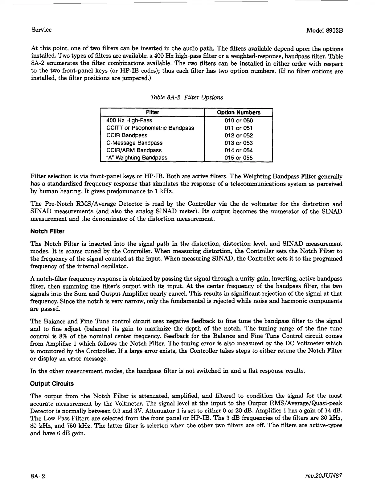
At
this point, one of
two
filters can be inserted in the audio path. The filters available depend upon the options
installed. Two types of filters are available: a
400
Hz
high-pass filter
or
a weighted-response, bandpass filter. Table
8A-2 enumerates the filter combinations available. The
two
filters can be installed
in
either order with respect
to the
two
front-panel keys
(or
HP-IB codes); thus each filter has
two
option numbers. (If no filter options are
installed, the filter positions are jumpered.)
Option Numbers
010
or
050
Table
8A-2.
Filter Options
CClTT
or Psophornetric Bandpass
CClR
Bandpass
C-Message Bandpass
CCIR/ARM Bandpass
“A”
Weiahtina BandDass
011
or
051
012
or
052
013
or
053
014
or
054
015
or
055
Filter selection is via front-panel keys
or
HP-IB. Both are active filters. The Weighting Bandpass Filter generally
has a standardized frequency response that simulates the response of a telecommunications system
as
perceived
by human hearing. It gives predominance
to
1
kHz.
The Pre-Notch RMS/Average Detector is read by the Controller via the
dc
voltmeter for the distortion and
SINAD measurements (and also the analog SINAD meter).
Its
output becomes the numerator of the SINAD
measurement and the denominator
of
the distortion measurement.
Notch Filter
The Notch Filter is inserted into the signal path in the distortion, distortion level, and SINAD measurement
modes. It is coarse tuned by the Controller. When measuring distortion, the Controller sets the Notch Filter
to
the frequency of the signal counted at the input. When measuring SINAD, the Controller sets it
to
the programed
frequency of the internal oscillator.
A
notch-filter frequency response is obtained by passing the signal through
a
unity-gain, inverting, active bandpass
filter, then summing the filter’s output with its input.
At
the center frequency of the bandpass filter, the
two
signals into the Sum and Output Amplifier nearly cancel. This results in significant rejection of the signal at that
frequency. Since the notch is very narrow, only the fundamental
is
rejected while noise and harmonic components
are passed.
The Balance and Fine Tune control circuit uses negative feedback
to
fine tune the bandpass filter to the signal
and
to
fine adjust (balance) its gain to maximize the depth of the notch. The tuning range of the fine tune
control is
8%
of the nominal center frequency. Feedback for the Balance and Fine Tune Control circuit comes
from Amplifier
1
which follows the Notch Filter. The tuning error
is
also measured by the
DC
Voltmeter which
is monitored by the Controller. If a large error exists, the Controller takes steps
to
either retune the Notch Filter
or
display an error message.
In the other measurement modes, the bandpass filter
is
not switched
in
and
a
flat response results.
Output Circuits
The output from the Notch Filter is attenuated, amplified, and filtered to condition the signal for the most
accurate measurement by the Voltmeter. The signal level at the input to the Output RMS/Average/Quasi-peak
Detector
is
normally between
0.3
and
3V.
Attenuator
1
is
set
to
either
0
or
20
dB.
Amplifier
1
has
a gain
of
14
dB.
The Low-Pass Filters are selected from the front panel
or
HP-IB. The 3
dB
frequencies of the filters are
30
kHz,
80 kHz, and
750
kHz. The latter filter
is
selected when the other
two
filters are
off.
The filters are active-types
and have
6
dB
gain.
8A-2
rev.20JUN87
 Loading...


