Model 8903B Service
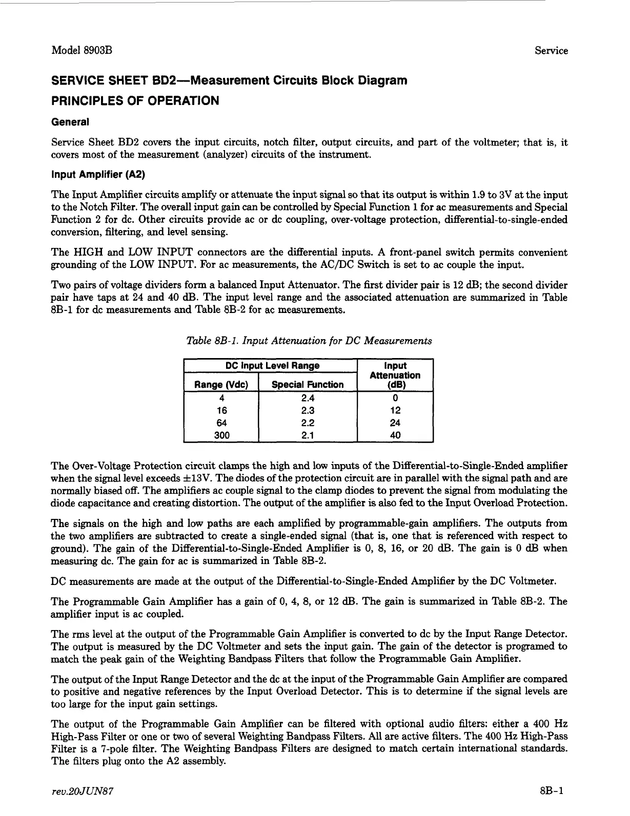
DC
Input Level Range
Range vdc) Special Function
4 2.4
16 2.3
64 2.2
300 2.1
SERVICE SHEET
BD2-Measurement Circuits
Block
Diagram
PRINCIPLES
OF
OPERATION
Input
Attenuation
(dB)
0
12
24
40
General
Service Sheet BD2 covers the input circuits, notch filter, output circuits, and part of the voltmeter; that is,
it
covers most of the measurement (analyzer) circuits of the instrument.
Input Amplifier (A2)
The Input Amplifier circuits amplify
or
attenuate the input signal
so
that
its
output
is
within 1.9
to
3V at the input
to the Notch Filter. The overall input gain can be controlled by Special Function
1
for ac measurements and Special
Function
2
for
dc. Other circuits provide ac
or
dc coupling, over-voltage protection,
differential-to-single-ended
conversion, filtering, and level sensing.
The HIGH and LOW INPUT connectors
are
the differential inputs.
A
front-panel switch permits convenient
grounding of the LOW INPUT.
For
ac measurements, the AC/DC Switch is set to ac couple the input.
Two pairs of voltage dividers form a balanced Input Attenuator. The first divider pair
is
12
dB;
the second divider
pair have taps at 24 and 40
dB.
The input level range and the associated attenuation are summarized in Table
8B-1 for dc measurements and Table 8B-2 for ac measurements.
Table
8B-1.
Input Attenuation
for
DC
Measurements
The Over-Voltage Protection circuit clamps the high and low inputs
of
the
Differential-to-Single-Ended
amplifier
when the signal level exceeds f13V. The diodes of the protection circuit are in parallel with the signal path and are
normally biased
off.
The amplifiers ac couple signal
to
the clamp diodes
to
prevent the signal from modulating the
diode capacitance
and
creating distortion. The output
of
the amplifier
is
also
fed
to
the Input Overload Protection.
The signals on the high and low paths are each amplified by programmable-gain amplifiers. The outputs from
the
two
amplifiers are subtracted
to
create a single-ended signal (that
is,
one that
is
referenced with respect
to
ground). The gain of the
Differential-to-Single-Ended
Amplifier
is
0,
8,
16,
or
20
dB.
The gain
is
0
dB
when
measuring dc. The gain for ac
is
summarized in Table 8B-2.
DC measurements are made at the output of the
Differential-to-Single-Ended
Amplifier by the DC Voltmeter.
The Programmable Gain Amplifier has a gain of
0,
4, 8,
or
12
dB.
The gain is summarized in Table 8B-2. The
amplifier input
is
ac coupled.
The
rms
level at the output of the Programmable Gain Amplifier is converted
to
dc by the Input Range Detector.
The output is measured by the DC Voltmeter and sets the input gain. The gain
of
the detector is programed
to
match the peak gain of the Weighting Bandpass Filters that follow the Programmable Gain Amplifier.
The output of the Input Range Detector and the dc at the input of the Programmable Gain Amplifier are compared
to positive and negative references by the Input Overload Detector. This
is
to determine
if
the signal levels are
too
large for the input gain settings.
The output of the Programmable Gain Amplifier can be filtered with optional audio filters: either a 400 Hz
High-Pass Filter
or
one
or
two
of
several Weighting Bandpass Filters. All are active filters. The 400
Hz
High-Pass
Filter
is
a 7-pole filter. The Weighting Bandpass Filters are designed
to
match certain international standards.
The filters plug onto the
A2
assembly.
reu.2OJUN87
8B-1
 Loading...


