Service Model 8903B
Range
(Vrms)
300
1 89
119
75.4
47.6
30.0
18.9
11.9
7.45
4.76
3.00
1.89
1.19
0.745
0.476
0.300
0.1 89
0.119
0.0745
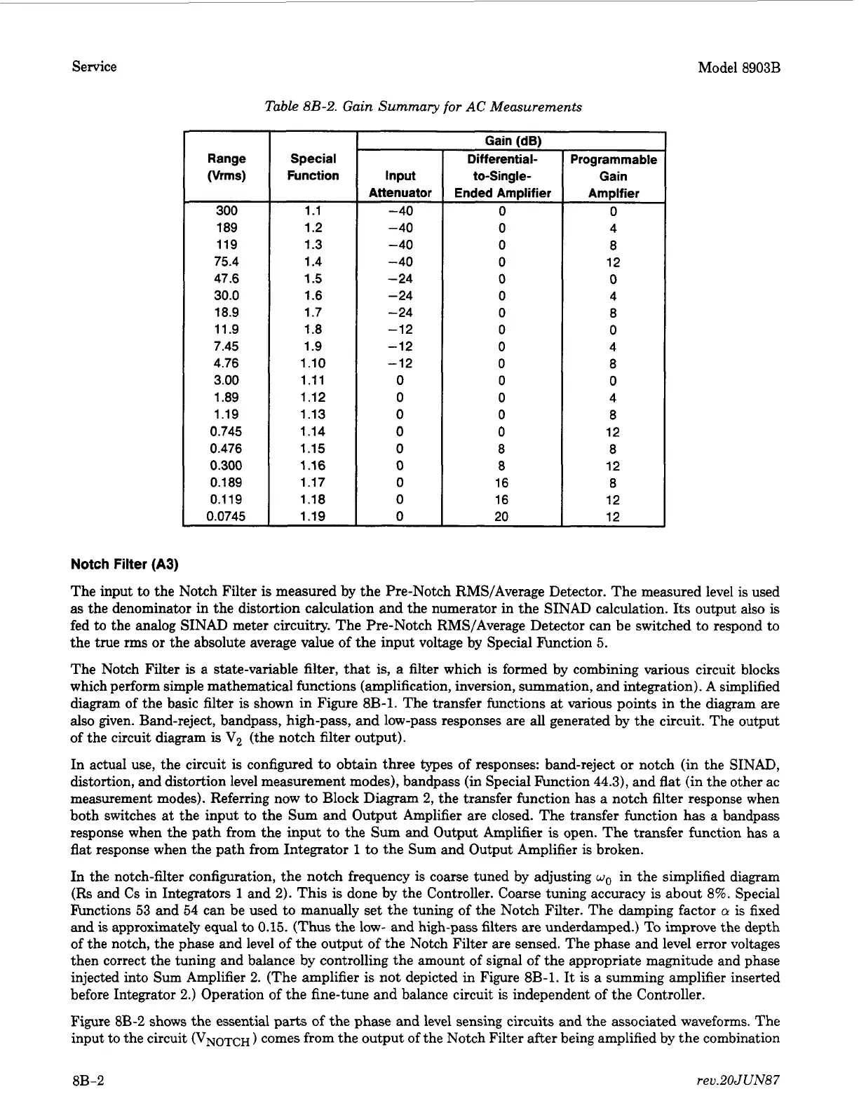
Table
8B-2.
Gain Summary
for
AC
Measurements
Special
Function
1.1
1.2
1.3
1.4
1.5
1.6
1.7
1.8
1.9
1.10
1.11
1.12
1.13
1.14
1.15
1.16
1.17
1.18
1.19
Gain IdB)
Input
Attenuator
-40
-40
-40
-40
-
24
-24
-
24
-12
-12
-12
0
0
0
0
0
0
0
0
0
..
Differential-
to-Single-
Ended Amplifier
0
0
0
0
0
0
0
0
0
0
0
0
0
0
8
8
16
16
20
Programmable
Gain
Amplfier
0
4
8
12
0
4
8
0
4
8
0
4
8
12
8
12
8
12
12
Notch
Filter
(A3)
The input to the Notch Filter
is
measured by the Pre-Notch RMS/Average Detector. The measured level is used
as the denominator in the distortion calculation and the numerator
in
the SINAD calculation.
Its
output also
is
fed
to
the analog SINAD meter circuitry. The Pre-Notch RMS/Average Detector can be switched to respond to
the true
rms
or
the absolute average value of the input voltage by Special Function 5.
The Notch Filter
is
a state-variable filter, that is, a filter which is formed by combining various circuit blocks
which perform simple mathematical functions (amplification, inversion, summation, and integration). A simplified
diagram of the basic filter is shown in Figure
8B-1.
The transfer functions at various points in the diagram are
also given. Band-reject, bandpass, high-pass,
and
low-pass responses are all generated by the circuit. The output
of the circuit diagram
is
V2
(the notch filter output).
In actual use, the circuit
is
configured
to
obtain three types of responses: band-reject
or
notch (in the SINAD,
distortion, and distortion level measurement modes), bandpass (in Special Function
44.3),
and flat (in the other ac
measurement modes). Refemng now to Block Diagram
2,
the transfer function has a notch filter response when
both switches at the input to the Sum and Output Amplifier are closed. The transfer function has a bandpass
response when the path from the input to the
Sum
and Output Amplifier
is
open. The transfer function has a
flat
response when the path from Integrator
1
to the Sum and Output Amplifier is broken.
In the notch-filter configuration, the notch frequency is coarse tuned by adjusting
wo
in the simplified diagram
(Rs and Cs in Integrators
1
and
2).
This
is
done by the Controller. Coarse tuning accuracy is about 8%. Special
Functions 53 and 54 can be used to manually set the tuning of the Notch Filter. The damping factor
o
is
fixed
and
is
approximatety equal
to
0.15.
(Thus
the low- and high-pass filters are underdamped.) To improve the depth
of the notch, the phase and level
of
the output of the Notch Filter are sensed. The phase and level error voltages
then correct the tuning and balance by controlling the amount of signal
of
the appropriate magnitude and phase
injected into Sum Amplifier
2.
(The amplifier
is
not depicted in Figure 8B-1.
It
is a summing amplifier inserted
before Integrator
2.)
Operation
of
the fine-tune and balance circuit is independent of the Controller.
Figure
8B-2
shows the essential parts
of
the phase and level sensing circuits and the associated waveforms. The
input to the circuit
(VNOTCH
)
comes from the output of the Notch Filter after being amplified by the combination
8B-2
rev.20JUN87
 Loading...


