Model
8903B
Service
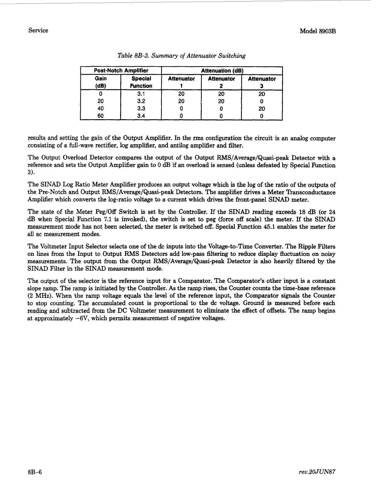
Post-Notch Amplifier
Gain Special
(dB)
Function
0
3.1
20
3.2
40 3.3
60
3.4
Attenuation
(dB)
Attenuator
Attenuator Attenuator
1
2
3
20
20
20
20
20
0
0
0
20
0
0
0
results and setting the gain of the Output Amplifier. In the
rms
configuration the circuit is an analog computer
consisting of a full-wave rectifier, log amplifier, and antilog amplifier and filter.
The Output Overload Detector compares the output of the Output RMS/Average/Quasi-peak Detector with a
reference and sets the Output Amplifier gain
to
0
dB
if an overload is sensed (unless defeated by Special F’unction
3).
The SINAD Log Ratio Meter Amplifier produces an output voltage which
is
the log of the ratio of the outputs of
the Pre-Notch and Output RMS/Average/Quasi-peak Detectors. The amplifier drives
a
Meter Transconductance
Amplifier which converts the log-ratio voltage
to
a current which drives the front-panel SINAD meter.
The
state
of the Meter Peg/Off Switch
is
set by the Controller.
If
the SINAD reading exceeds
18
dB
(or
24
dB
when Special Function
7.1
is
invoked), the switch is set
to
peg (force
off
scale) the meter.
If
the SINAD
measurement mode has not been selected, the meter is switched
off.
Special F’unction
45.1
enables the meter for
all ac measurement modes.
The Voltmeter Input Selector selects one of the dc inputs into the Voltage-to-Time Converter. The Ripple
Filters
on lines from the Input to Output RMS Detectors add low-pass filtering
to
reduce display fluctuation on noisy
measurements. The output from the Output RMS/Average/Quasi-peak Detector
is
also
heavily filtered
by
the
SINAD
Filter in the SINAD measurement mode.
The output of the selector
is
the reference input for a Comparator. The Comparator’s other input
is
a constant
slope ramp. The ramp
is
initiated by the Controller.
As
the ramp rises, the Counter counts the time-base reference
(2
MHz). When the ramp voltage equals the level of the reference input, the Comparator signals the Counter
to stop counting. The accumulated count
is
proportional
to
the dc voltage. Ground
is
measured before each
reading and subtracted from the
DC
Voltmeter measurement
to
eliminate the effect of offsets. The ramp begins
at approximately -6V, which permits measurement of negative voltages.
8B
-6
reu.2OJUN87
 Loading...


